Do you have a question about the COOK SQN Series and is the answer not in the manual?
Inspect fan and accessories for damage and shortage upon receipt. Check wheel rotation and dampers.
Lift the fan by the designated lifting holes. Never lift by the shaft, motor, or housing.
Fans should be installed and serviced by qualified personnel. Disconnect power before work.
Refers to external supplements for EC or VF2 motor wiring.
Wiring for single speed, single phase motors, including grounding and reversal.
Wiring for 2-speed, 2-winding single phase motors, including grounding and reversal.
Wiring for dual voltage single phase motors, including grounding and reversal.
Wiring diagram for 3-phase, 9-lead Y-connected motors, including reversal.
Wiring diagram for 3-phase, 9-lead delta-connected motors, including reversal.
Wiring for 2-speed, 1-winding 3-phase motors requiring magnetic control.
Wiring for 2-speed, 2-winding 3-phase motors, including reversal for each speed.
Schematic showing typical damper motor connections for single and 3-phase applications.
Instructions for mounting motors (3 HP and larger, or heavy) that are shipped loose.
General guidelines for wiring installation, referencing NEC and diagrams.
Instructions for wiring the electrical box on the blower housing for direct drive units.
Wiring instructions for belt drive units, including slack and motor removal.
Guidance on belt tension, pulley adjustment, and alignment for belt-driven fans.
Details on adjusting pulley alignment using set screws and checking for gaps.
Steps to perform before starting the fan, including power lockout and fastener checks.
Inspect bolts, setscrews, and motor mounting bolts after 30 minutes of operation.
Inspect belt alignment and tension after 8 hours of operation.
Inspect belt tension after 24 hours of operation.
Inspect bolts, belts, bearings, and cleanliness regularly as per recommendations.
Guidelines for relubricating fan bearings based on operating conditions and RPM.
Potential causes for low fan capacity or pressure, including rotation and inlet conditions.
Causes of excessive vibration and noise, such as unbalanced wheels, belts, or bearings.
Troubleshooting steps for an overheated motor, including wiring, rotation, and voltage.
Potential causes for overheated bearings, such as lubrication or belt tension issues.
| Model | SQN Series |
|---|---|
| Power Consumption | Varies by model |
| Noise Level | Varies by model |
| Frequency | 60 Hz |
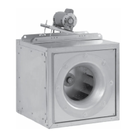
| Material | Galvanized Steel |
| Weight | Varies by model |