Do you have a question about the COOK XLWH/XMWH and is the answer not in the manual?
Read this publication and supplemental documents before installation or maintenance.
Inspect the unit and accessories for damage or shortage upon receipt.
Lift fans by attachment to the power assembly or shipping carton, not by shaft or motor.
Coat shafts with grease, store in original crate, protect from elements.
Wall opening size varies by mounting type; refer to submittal drawings for dimensions.
Mount motors (5 HP+) and heavy motors to the motor mounting plate.
Disconnect power, use lockout/tagout, place disconnect switch near fan.
Adjust belt tension by moving the motor plate; proper tension has 1/4" deflection per foot.
Do not change pulley pitch diameter to adjust tension; this changes fan speed.
Align pulleys by loosening motor pulley setscrew and moving pulley on shaft.
Insert fan into wall opening, secure with fasteners, ensure motor base is below fan shaft.
Follow local ordinances, NEC, wiring diagrams; ensure correct voltage and frequency.
Label circuits, identify closed switches, follow safety practices.
Extend wires, prevent excess wire entry into fan area.
Remove end panel or extend wires through side panel for access.
Remove end guard, drill hole for wires, restrain incoming wire.
Diagram showing connections for single speed, single phase motors.
Diagram showing connections for 2-speed, 2-winding single phase motors.
Diagram for dual voltage single speed, single phase motors.
Schematic for typical damper motor applications.
Wiring diagram for 3-phase, 9-lead Y-connected motors.
Wiring diagram for 3-phase, 9-lead delta-connected motors.
Wiring diagram for 2-speed, 1-winding 3-phase motors.
Wiring diagram for 2-speed, 2-winding 3-phase motors.
Seal shutter flange with caulking for weather protection.
Position shutter in the wall opening.
Mount shutter using sheet metal screws on six-inch centers.
Manually operate shutter to ensure blades move freely.
Ensure correct rotation to prevent motor overheating and damage.
Procedures and checks for operating the fan.
Checklist for ensuring fan safety and readiness before startup.
Start fan at lowest speed and inspect for issues.
Torque values for setscrews and hold-down bolts.
Schedule inspections at 30-minute, 8-hour, and 24-hour intervals.
Establish a regular inspection schedule based on operating conditions.
Inspect fans in contaminated environments more frequently.
Use NLGI grade 2 lithium-based grease; specific types for motors and fans.
Prelubricated bearings; follow motor nameplate or add light mineral oil after 3 years.
Intervals for motor bearing relubrication based on frame size, RPM, and conditions.
Relubricate fan bearings per the conditions chart, preferably while running.
Chart detailing greasing intervals based on RPM, temperature, and conditions.
Contact Loren Cook or authorized service for defective motors within warranty.
Adjust pulley grooves to change fan speed; ensure proper belt tension.
Open pulley to ride belt deeper for reduced speed.
Close pulley for belt to ride higher; maintain RPM and horsepower limits.
Tables showing maximum RPM for various fan models and sizes.
Detailed instructions for removing and replacing fan bearings.
Causes for low capacity or pressure issues.
Causes for excessive vibration and noise.
Potential causes for motor overheating.
Table providing installation dimensions for various fan types.
Installation of exhaust fan in masonry wall with shutter guard.
Chart of dimensions for various fan models with accessories.
Diagrams identifying parts for various XW, XP, XPHD, XWHD series fan models.
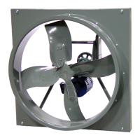
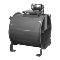
Diagrams identifying parts for XLW, XMW, XLWH, XMWH series fan models.
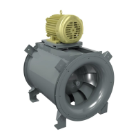
Diagrams identifying parts for XLP, XLPH, XMP, XMPH series fan models.
Diagrams identifying parts for AWD, AWB, APD, APB series fan models.
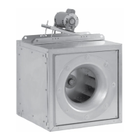
Diagrams identifying parts for EWD series fan models.
Diagrams identifying parts for EWB series fan models.
Diagrams identifying parts for EPD series fan models.
Diagrams identifying parts for EPB series fan models.
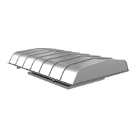
Diagram and parts list for weather hood, sizes 36 to 60.
Diagram and parts list for weather hood, sizes 8 to 30.
Diagram and parts list for weather hood, EWB 72.
One-year warranty for parts, excluding shipping costs.
Conditions that void the warranty, such as misuse or alteration.
Procedure for submitting a warranty claim with company contact details.
Motor manufacturer warranty applies; contact authorized service stations.