EasyManua.ls Logo

Coolmay EX3G Series - User Manual

Coolmay EX3G Series
2 pages
Print Icon
To Next Page IconTo Next Page
Loading...
Thank you for purchasing Coolmay EX3G HMI PLC All-in-One products. This manual mainly explains the
product features, specifications and wiring methods. Detailed PLC programming, please refer to “Coolmay EX3G
HMI PLC All-in-One Programming Manual”. Detailed HMI part, refer to “Coolmay HMI Programming Manual”.
HMI optional RS232/RS485
FG 0V 24V
Electric Design
Product structure
RUN: PLC operating
indicator
COM: flash when PLC
communicates
with HMI
Y20
COM4
Y17
Y16
Y15
Y14
COM3
Y13
Y12
Y11
Y10
COM2
Y07
Y06
Y05
Y04
COM1
Y03
Y02
Y01
Y00
COM0
X23
X22
X21
X20
X17
X16
X15
X14
X13
X12
X11
X10
COM
X07
X06
X05
X04
X03
X02
X01
X00
COM
Graph 5 EX3G-70KH
PLC programming port
(optional RS485/WIFI)
Network port (optional)
Graph 6 EX3G-100HA
X23
X22
X21
X20
COM
X16
X15
X14
X13
X12
X11
X10
COM
X07
X06
X05
X04
X03
X02
X01
X00
COM
Y23
Y22
Y21
Y20
Y17
Y16
Y15
Y14
COM3
Y13
Y12
Y11
Y10
COM2
Y07
Y06
Y05
Y04
COM1
Y03
Y02
Y01
Y00
COM0
Hardware Interface
AD1
AD2
AD3
AD4
GND
DA0
DA1
EX3G-70KH
EX3G-43HB/H
Mechanical Design
Input ON
Input OFF
Filter function
High-speed counting
With filter function, the filter time can be set among 0-60ms,
defaulted as 10ms
Digital relay output index
Max current
Circuit power voltage
Circuit insulation
On response time
Mechanical life without load
Electric life with rated load
5A
DC/AC 24V-220V
Relay mechanical insulation
Approx. 10ms
10 million times
300,000 times
Digital transistor(MOS) output index
Max current
Circuit power voltage
Circuit insulation
Isolated voltage (power-terminal)
On response time
High-speed output frequency
500mA(MOS 2A)
DC24V
Optocoupler insulation
1500VAC
High-speed output: 10μs, and others 0.5ms
Analog input indexes
Input signal
Response time
Analog input
Precision
PT100/PT1000/thermocouple/NTC/0-10V/0-5V/-10V~10V/-5V~5V/0-20mA/4-20mA/ customizations.
1 scanning cycle
0-16 channels
12 bits
Analog output indexes
Output signal
Analog output indexes
Precision
0-5V/0-10V/0-20mA/ customizations
0-8 channels
12 bits
External port
COM port
Environment
Operating temperature
Relative humidity
Storage temperature
Vibrational frequency
0°C~50°C
5%~95%RH
-20°C~70°C
10-57Hz, amplitude 0.035mm, 57Hz-150Hz, 4.9m/s²
(10 times each on X, Y, Z, total 80 minutes each)
EX3G HMI PLC All-in-One User Manual
Chart 3: Mounting dimension
Model
Max digital
points
Mounting dimension
Boundary dimension
W*H*D(mm)
A(mm) B(mm)
EX3G-43HB
EX3G-70H
EX3G-100HA
12DI/12DO
24DI/20DO
30DI/30DO
119
194
261
93
138
180
134*102*30
212*148*40
275*194*36
Four side mounting holes
Terminal block of power
supply
FG: cover protection GND
0V: 24V negative
24V: 24V positive
Terminal block of DO
Terminal block of DI
USB port (not available
for HB series)
PWR: power indicator
HMI programming port
PLC programming
port/RS485/RS232
PLC operating switch
RUN/STOP
AD
DA
HMI RS232/RS485/CAN
LCD
Network port (HMI/PLC)
PLC USB programming port
EX3G-43KH(50)KH
12DI/12DO
143
86
150*93*32
EX3G-43(50)KH
6
13
6
13
Graph 2 Product structure
More specs can be customized if bulk order.
Max analog
quantity
4AD/2DA
12AD/8DA
16AD/8DA
4AD/2DA
Wiring specifications of terminals: 22-14AWG wire. The terminals of this serial are all pluggable ones.
Definition of communication interface : Refer to Chart 4:Pin definition
The features are as below.
Super functions.
Its PLC is compatible with FX3G, FX3U, FX3S. It operates fast.
Highly integration.
1. The digital points are 30 inputs and 30 outputs at most. The digital output can be transistor, relay or mixed
output. Analog can reach up to 16 input and 8 output. It has 2 PLC COM port (RS232 and Mini B-type USB
port), 1 downloading port and 1 USB port on HMI.
2. The PLC part of models 70KH, 100HA all-in-one can optionally select one 485 port or two 485 ports
(one is changed from existed 232 port), CAN, network port (not coexist with the one on HMI), Wifi (will cover
the existed 232 port). The HMI part can optionally select one RS232 or one RS485, and network port (not
coexist with the one on PLC).
3. The PLC part of models 43HB, 43(50)KH can optionally select two RS485, and HMI part can
select one RS232.
Support several high-speed counting and high-speed pulse.
1. Commonly high-speed conting is 6-channel single phase 60KHz or AB(Z)2-channel 60KHz plus 1
channel 10KHz.
2. High-speed pulse is commonly 8 channels, HB series Y0-Y7 10KHz per channel,
Acceleration and deceleration are independent.
3. The total high-speed counting and pulse can not exceed 480KHz.
32K steps program capacity, 32K power-off retentive registers, support interrupt, linear and circular
interpolation, PID self-adjusting.
Special encryption.
Set password as 12345678 to thoroughly prevent reading data.(PLC only supports 8-bit password encryption)
PLC is compatible with Mitsubishi programming software, and HMI is Coolmay HMI programming
software.
More models are supported to customize if bulk order.
X24
X26
X25
X27
Y21
Y22
Y23
Operation switch
X17
X27
X26
X25
X24
X30
X31
X32
X33
X34
X35
GND1
Y35
Y34
Y33
Y32
Y31
Y27
COM5
Y26
Y25
Y24
Y30
AD5
AD6
AD7
AD8
AD9
AD10
AD12
AD13
AD14
AD15
AD0
AD1
AD2
AD3
AD4
AD11
GND
GND1
DA0
DA1
DA3
DA7
DA4
DA5
DA6
DA2
AD0
EX3G-100HA-44M-16AD8DA
EX3G-100HA-60M-5AD2DA
AD1
AD2
AD3
AD4
GND
DA0
DA1
X30
X31
X32
X33
X34
X35
GND1
Y35
Y34
Y33
Y32
Y31
Y27
COM5
Y26
Y25
Y24
Y30
AD5
AD6
AD7
AD8
AD9
AD10
AD12
AD13
AD14
AD15
AD0
AD1
AD2
AD3
AD4
AD11
GND
GND1
DA0
DA1
DA3
DA7
DA4
DA5
DA6
DA2
AD0
EX3G-70KH-44M-16AD8DA
EX3G-70KH-60M-5AD2DA
High-speed input: current>5.8mA/24V
Common input: current >9.9mA/24V
High-speed input: current<4.5mA/19V
Common input: current >4mA/17V
Input level
Sink NPN, com isolation, S/S
Output level
Low level NPN, COM connects negative
Output level
Dry contact, COM connects positive or negative
8 channels
H/KH/HA Y0-Y3 100KHz, Y4-Y7 10KHz.
Acceleration and deceleration are independent.The total high-speed
counting and pulse can not exceed 480KHz.
. HB series Y0-Y7 10KHz per channe.l
Commonly it is 6 single 0KHz
for HB series, 1 , or 3 AB 10KHz, or
2 ABZ 10KHz + 1 AB 10KHz. H/KH/HA series can be 6 single phase 60KHz,
or 2 AB(Z) 60KHz + 1 AB 10KHz.
Refer to "Chart 1: basic parameter".
1
2
3
4
5
6
7
8
9
10
11
12
13
14
15
Product Details
1 EX3G
2 43HB/43KH/43KHB: 4.3 50KH: 5 70KH: 7 100HA: 10
3
4
5
6
7
8 : , ,
: : , :
: : : :
_: - ~ _: - ~ ( _ _)
9
_: - ~ _: - ~
( / , )
10 , C3- ABZ phase counting.
for HB series, 1 , or 3 AB 10KHz, or 2 ABZ 10KHz + 1 AB 10KHz.
H/KH/HA series can be 6 single phase 60KHz, or 2 AB(Z) 60KHz + 1 AB 10KHz.
11 - - ,
.
12 Refer to "Chart 1: basic parameter".
.
.
.
.
.
.
.
.
.
.
.
.
Series
HMI
Digital input and output (DI/DO) 10(5DI/5DO), 24(12DI/12DO), 44(24DI/20DO), 60(30DI/30DO), etc.
Module type M- Main module of universal controller
Digital output (DO) type R- relay T- transistor RT- both relay and transistor
Analog input (AD) 4 channels for 43H, 12 for 70H/100H
Analog output (DA) 2 channels for 43H, 8 for 70H/100H
AI type E Thermocouple E (can be customized as type K T, S or J supports negative temperature),
PT PT100, PT1000 PT1000 NTC thermistor 10K, 50K, 100K
A0 0-20mA A4 4-20mA V 0-10V V5 0-5V
V5 5V 5V V 10V 10V only 7 and 10 inch support V5 and V
AO type A0- 0-20mA A4- 4-20mA V- 0-10V V5- 0-5V
V5 5V 5V V 10V 10V
only 70KH 100HA support negative voltage covers 2 channels
C1- singe phase high-speed counting, C2- AB phase counting
Commonly it is 6 single 0KHz
P- high-speed pulse; Commonly EX3G 43HB is 8 channel 10KHz, and for other models Y0-Y3 is 100KHz,
Y4-Y7 is 10KHz That high speed counting plus high speed pulse must be within 480KHz.
Naming rules
EX3G
43HB
Basic parameter
Specifications of
HMI PLC All-in-One
EX3G-43HB(H)/43(50)KH-16M
EX3G-70KH/100HA-16M
EX3G-43HB(H)/43(50)KH-24M
EX3G-70KH/100HA-24M
EX3G-70KH/100HA-44M
Digital
points
Analog points
(optional)
COM port
(optional)
High-speed counting
(optional)
High-speed pulse
(optional)
DI
DO
AD DA
HMI
PLC
Single
phase
AB
phase
Output
12 12
12 12
24
20
43HB(H)/43(50)KH:MT is MOS output,max load 2A.
70H/ 70KH/100HA:MT is transistor output (Y0-Y3 are MOS outputs) with max load 500mA. MR is relay output with max load
5A. MRT is mixed output.
Chart 1: basic parameter
485P/232H
-
1P
-
1C1
A0
V
2DA
4ADRTM
24
------
Electric parameter
Input voltage
DC24V
Chart 2: electric parameter
8
8
8
8
EX3G-70KH/100HA-60M
30
30
1 2
3
4
5
6
7
8 9
11
10
12
EX3G-43HB/
43 : 2x 485 port
EX3G-70KH/100HA: 1x 485 or
2x 485 (one is changed from the existed 232),
CAN, network port (can't coexist with the one
on HMI), Wifi (cover the existed 232 port)
43H 50
KH/ ( )
EX3G-43HB/43(50)KH: 1x 232 port.
EX3G-70KH/100HA: 1x 232 port
or 485 port, network port (can't coexist with the
one on PLC)
H
/
KH/HA
:
6-channel
60KHz
HB
:
6
-channel
10KHz.
8 channels
.
H/
KH/
HA
:
Y0-
Y3
is
100KHz,
Y4
-
Y7
is
10KHz
.
HB
:
Y0-Y7 is 10KHz
per channel
.
Acceleration and
deceleration are
independent.
High-speed
counting and pulse
can't over
480KHz.
Digital input indexes
ABZ
phase
Isolation mode
Photocoupling
Input impedance
High-speed input 3.3KΩ
Common input 4.3Ω
6
13
USB port/optional SD card
HMI download port
PLC USB
programming port
PLC USB
programming port
Operation switch
USB port/optional SD card
HMI download port
Network port (optional)
FG 0V 24V
PLC programming port
(optional RS485/WiFi)
Automation Expert
1
4
11
10
3
2 8
5
9
7
16
1
4
10
11
3
2
8
5
7
9
16
10
11
12
1
4
3
2
8
14
7
5
15
9
16
16
Wifi
COM4
16
8
4
2
4
2
16
8
16
8
5
2
H/KH
/
HA:
2-channel
60KHz
and
1
-
channel
10KHz
HB
:
3
-channel
10KHz
.
H/
KH
/HA
:
2
ABZ
60KHz
HB:
2
ABZ
10KHz.
Note: A/B,A1/B1
is Rs485
Graph 7
COM1/COM2
EX3G-70H-16M
EX3G-70H-24M
EX3G-70H-38M
EX3G-70H-44M
12 12
8 8
20 18
24
20
8 6
12
8
Graph 1 Mounting dimension
EX3G-100HA
EX3G-43HB/H
EX3G-70KH
EX3G-43(50)KH
35.6
163
5
226
194
275
36
102
120
32
150
93
32
86
143
134
94
217
154
262
180
EX3G-70H
148
212
40
194
138
※ 更
EX3G-100HA
6
13
1
10
11
9
4
3
2
5
7
8
14
12
15
16
13 6
10
11
EX3G-70H
3
2
15
8
14
9
7
5
1
4
8
FG 0V 24V
PLC progrm port/
optional HMI 232 port
HMI download port
PLC operating switch
EX3G
-
43HB
/
H
Graph3
DA0
DA1
GND
AD0
AD1
AD2
AD3
GND
B A
Y13
Y12
Y11
Y10
Y07
Y06
Y05
Y04
Y03
Y02
Y01
Y00
COM
USB port/
optional SD card
(HB can't support)
X13
X12
X11
X10
X07
X06
X05
X04
X03
X02
X01
X00
COM
FG 0V 24V
Y13
Y12
Y11
Y10
Y07
Y06
Y05
Y04
Y03
Y02
Y01
Y00
COM
DA0
DA1
GND
AD0
AD1
AD2
AD3
GND
B A
X13
X12
X11
X10
X07
X06
X05
X04
X03
X02
X01
X00
COM
Graph 4 EX3G-43 KH(50)
PLC USB program port
FG 0V 24V
RS232/RS485(optional)
HMI download port
Y21
Y20
Y17
Y16
Y15
Y14
COM3
Y13
Y12
Y11
Y10
COM2
Y07
Y06
Y05
Y04
COM1
Y03
Y02
Y01
Y00
COM0
X23
X22
X21
X20
X17
X16
X15
X14
X13
X12
X11
X10
COM
X07
X06
X05
X04
X03
X02
X01
X00
COM
Graph 5 EX3G-70H
PLC operating switch
PLC prgram por t
X24
X25
X26
X27
AD07
AD05
AD00
GND
GND
DA00
DA06
A
B
Y22
Y23
AD06
AD04
AD03
AD02
AD01
DA01
DA02
DA03
DA04
DA05
DA07
PLC download port
EX3G-70KH
30DI/30DO
217 154 226*163*35.6
16AD/8DA
PLC USB program port
PLC progrm port/
optional HMI 232 port
PLC operating switch
HMI download port
USB port/
optional SD card
Ethernet port (optional)
USB port/optional SD card
Question and Answer IconNeed help?

Do you have a question about the Coolmay EX3G Series and is the answer not in the manual?

Summary

EX3 G HMI PLC Electric Design

EX3 G HMI PLC Product Structure

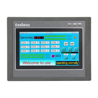
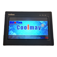
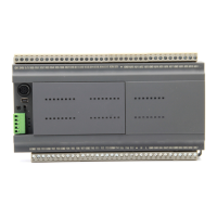
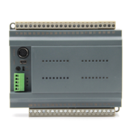
Details the physical layout and component arrangement of the EX3G HMI/PLC.

EX3 G HMI PLC Hardware Interface

EX3 G HMI PLC USB Programmer Port

Describes the dedicated port for programming the PLC via USB connection.

EX3 G HMI PLC Basic Specification Parameters

EX3 G HMI PLC Input;Output Points

Lists the number of digital input and output points for different EX3G models.

EX3 G HMI PLC Output Types

Details the available output types, including relay and transistor outputs.

EX3 G HMI PLC Wiring and Circuits

EX3 G HMI PLC Equivalent Circuits

Illustrates equivalent circuits for relay and transistor outputs.

EX3 G HMI PLC Inductive Load Protection

Shows circuit diagrams for absorbing inductive load voltage.

EX3 G HMI PLC Pulse Output Wiring

Provides wiring diagrams for pulse output signals.

EX3 G HMI PLC Input Wiring

Illustrates typical input wiring configurations for the PLC.

EX3 G HMI PLC Analog Wiring

Details wiring methods for analog input signals.

EX3 G HMI PLC Programming Reference

EX3 G HMI PLC Device Allocation

Details device allocation and power-down retention for PLC elements.

EX3 G HMI PLC Analog Input Registers

Explains analog input registers and their direct/FROM demand read methods.

EX3 G HMI PLC Analog Output Registers

Specifies analog output registers and their configuration for voltage/current.

EX3 G HMI PLC Anti-Interference

EX3 G HMI PLC Anti-Jamming Processing

Provides methods for processing PLC inputs to prevent jamming and interference.

EX3 G HMI PLC Tips and Precautions

EX3 G HMI PLC General Safety Tips

Offers essential safety advice for installation and operation.

EX3 G HMI PLC Wiring and Cable Management

Guides on proper wiring, cable separation, and grounding for anti-interference.

Overview

EXIG HMI PLC All-in-One User Manual

This manual provides a comprehensive guide to the EXIG HMI PLC, an all-in-one device designed for industrial automation. It combines the functionalities of a Human-Machine Interface (HMI) and a Programmable Logic Controller (PLC) into a single unit, offering a streamlined solution for various control applications. The EXIG HMI PLC is compatible with FOGL, FOGU, FOGL II, and operates best when paired with these systems.

Function Description

The EXIG HMI PLC serves as a central control unit, integrating display, input, and output functionalities. It supports a wide range of digital and analog inputs and outputs, allowing for flexible connectivity with various sensors, actuators, and other industrial devices. The device can be configured to handle up to 32 digital inputs and 30 digital outputs, with the option to select either 485 or 232 communication protocols. This flexibility allows the EXIG HMI PLC to adapt to different communication requirements within an industrial environment.

The device also features a built-in real-time clock (RTC), which can be used for time-based control and data logging. The RTC is particularly useful for applications requiring precise timing and scheduling. The EXIG HMI PLC supports various communication protocols, including Modbus RTU, which enables seamless integration with other Modbus-compatible devices.

The HMI component provides a user-friendly interface for monitoring and controlling industrial processes. It features a graphical display that can be customized to show various process parameters, alarms, and control elements. The HMI supports touch input, allowing operators to interact with the system intuitively. The PLC component executes control logic based on programmed instructions, enabling automated control of machinery and processes. It supports various programming languages, including ladder logic, which is widely used in industrial automation.

The EXIG HMI PLC is designed to be a robust and reliable solution for industrial control. It features a durable enclosure that protects the internal components from harsh industrial environments. The device is also equipped with various safety features, including overcurrent protection and short-circuit protection, to ensure safe and reliable operation.

Usage Features

The EXIG HMI PLC offers several features that enhance its usability and flexibility. The device supports multiple communication channels, allowing for simultaneous communication with various devices. This is particularly useful in complex industrial systems where multiple devices need to be controlled and monitored. The EXIG HMI PLC also supports remote access, allowing operators to monitor and control the system from a remote location. This feature is especially beneficial for applications requiring remote monitoring and control, such as distributed control systems.

The device's programming environment is user-friendly, allowing for easy configuration and programming of the HMI and PLC components. The programming software provides a graphical interface that simplifies the creation of control logic and HMI screens. The software also includes various debugging tools, which help in identifying and resolving programming errors.

The EXIG HMI PLC supports a wide range of power supply options, allowing it to be used in various industrial environments. The device can be powered by either DC or AC power, depending on the specific model. This flexibility ensures that the EXIG HMI PLC can be integrated into existing power systems without requiring significant modifications.

The device's compact design makes it suitable for installation in space-constrained environments. The EXIG HMI PLC can be mounted on a DIN rail, which simplifies installation and reduces wiring complexity. The device also features a modular design, allowing for easy expansion and customization. This modularity enables users to add or remove modules as needed, adapting the EXIG HMI PLC to evolving application requirements.

The EXIG HMI PLC is designed for easy maintenance and troubleshooting. The device features diagnostic indicators that provide visual feedback on its operational status. These indicators help in quickly identifying and resolving issues, reducing downtime and improving overall system reliability. The device also supports firmware updates, allowing users to keep the system up-to-date with the latest features and bug fixes.

Maintenance Features

To ensure optimal performance and longevity of the EXIG HMI PLC, regular maintenance is recommended. This includes periodic cleaning of the device to prevent dust and debris buildup, which can affect its performance and lead to overheating. It is also important to regularly check the wiring connections to ensure they are secure and free from damage. Loose or damaged connections can lead to intermittent operation or system failures.

The EXIG HMI PLC's modular design simplifies component replacement. If a module fails, it can be easily replaced without requiring the replacement of the entire device. This reduces maintenance costs and minimizes downtime. The device also supports hot-swapping of certain modules, allowing for replacement without powering down the system.

For software maintenance, it is recommended to regularly back up the device's configuration and program files. This ensures that in case of a system failure or data loss, the configuration can be restored quickly. It is also important to keep the programming software updated to the latest version, as updates often include bug fixes and performance improvements.

The EXIG HMI PLC is designed to be a reliable and durable device, but in case of any issues, the user manual provides detailed troubleshooting guides. These guides help in diagnosing common problems and provide step-by-step instructions for resolving them. If the issue cannot be resolved using the troubleshooting guide, it is recommended to contact technical support for further assistance.

The device also features self-diagnostic capabilities, which can help in identifying internal faults. These diagnostics provide error codes or messages that can be used to pinpoint the cause of the problem. By understanding these error codes, users can take appropriate corrective actions or seek professional help if needed.

Regular calibration of analog input and output modules is also recommended to ensure accurate measurements and control. Over time, the accuracy of these modules can drift, leading to inaccurate readings or control actions. Calibration helps in restoring the accuracy of these modules, ensuring reliable system operation.

Finally, it is important to follow all safety guidelines and precautions when performing maintenance on the EXIG HMI PLC. This includes disconnecting power before performing any maintenance tasks and using appropriate personal protective equipment. Adhering to these safety guidelines helps in preventing accidents and ensuring a safe working environment.

Coolmay EX3G Series Specifications

General IconGeneral
SeriesEX3G Series
Power SupplyDC 24V
Operating Temperature0°C to 50°C
TypeController
Communication PortsRS232, RS485
PortsEthernet, RS232, RS485

Related product manuals