1
Form 6 Microprocessor-Based
Pole-Mount Recloser Control
Installation and Operation Instructions
Reclosers
Service Information
Safety Information ..................................................... 2
Product Information .................................................. 3
Introduction ............................................................ 3
ANSI Standards ...................................................... 3
Quality Standards ................................................... 3
Acceptance and Initial Inspection ........................... 3
Handling and Storage ............................................ 3
Control Power ........................................................ 3
Battery Replacement and Disposal ........................ 3
Operation Upon Loss of AC Power ........................ 4
Form 6 Recloser Control Description ...................... 5
Description ............................................................. 5
Theory of Operation ............................................... 5
Control Front Panel ................................................ 6
Control Features ..................................................... 11
Communications .................................................... 14
Control Information ................................................. 14
Control Back Panel ................................................ 14
Installation Procedure ............................................... 15
Initial Programming Prior to Installation ................... 15
Control / Recloser Compatibility ............................. 15
Duty Cycle Monitor ................................................. 16
Mounting the Control .............................................. 16
Locking the Control ................................................ 16
Control Cable ......................................................... 18
Grounding the Control ............................................ 18
Customer Connections for AC Power .................... 21
Before Placing Control and Recloser into Service .... 30
Using Removable Inserts ........................................ 31
Accessories ............................................................... 32
Low Voltage Closing ............................................... 32
Internal Voltage Sensing .......................................... 32
Incoming Power Receptacles ................................. 32
Cable Locking Sleeves ........................................... 32
120 VAC GFI Duplex Outlet .................................... 32
BCT Terminal Blocks Accessory .............................. 41
Auxiliary Terminal Block Accessory .......................... 41
Cabinet Ordering Accessories ................................ 41
Discrete Interface Board Option Accessory ............ 42
Radio Mounting Accessory ..................................... 42
Communication Board Accessories ........................ 42
Testing ........................................................................ 45
Testing an Installed Control .................................... 45
Remove the Control from Service ........................... 46
Preliminary Testing with No AC Available ................ 46
Testing with Type MET Tester ................................. 46
Closing the Recloser During Testing ....................... 47
Battery Test and Charging Procedures ................... 50
Return the Control to Service ................................. 52
Recloser VTC Interface ............................................. 52
Control VTC Interface ............................................... 53
Additional Information ............................................... 54
Replacement Kits ................................................... 54
Factory-Authorized Service Centers ....................... 54
Factory Maintenance Classes ................................. 54
Contents
S280-70-3
October 2012 • Supersedes 7/05
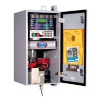
Figure 1.
Form 6 microprocessor-based pole-mount recloser control.
For Type F6-P2A Control,
and Type F6-P2B Control,
above Serial Number 10,000
or beginning with CP57.
•F6-P2AappliestoForm6controlfor
use with W, VS, and auxiliary-
powered NOVA reclosers.
•F6-P2Bappliestocontrol-powered
NOVA Form 6 control for use with
control-powered reclosers.