EasyManua.ls Logo

Cooper Power Systems Form 6 Series - User Manual

Cooper Power Systems Form 6 Series
56 pages
Print Icon
To Next Page IconTo Next Page
Loading...
1
Form 6 Microprocessor-Based
Pole-Mount Recloser Control
Installation and Operation Instructions
Reclosers
Service Information
Safety Information ..................................................... 2
Product Information .................................................. 3
Introduction ............................................................ 3
ANSI Standards ...................................................... 3
Quality Standards ................................................... 3
Acceptance and Initial Inspection ........................... 3
Handling and Storage ............................................ 3
Control Power ........................................................ 3
Battery Replacement and Disposal ........................ 3
Operation Upon Loss of AC Power ........................ 4
Form 6 Recloser Control Description ...................... 5
Description ............................................................. 5
Theory of Operation ............................................... 5
Control Front Panel ................................................ 6
Control Features ..................................................... 11
Communications .................................................... 14
Control Information ................................................. 14
Control Back Panel ................................................ 14
Installation Procedure ............................................... 15
Initial Programming Prior to Installation ................... 15
Control / Recloser Compatibility ............................. 15
Duty Cycle Monitor ................................................. 16
Mounting the Control .............................................. 16
Locking the Control ................................................ 16
Control Cable ......................................................... 18
Grounding the Control ............................................ 18
Customer Connections for AC Power .................... 21
Before Placing Control and Recloser into Service .... 30
Using Removable Inserts ........................................ 31
Accessories ............................................................... 32
Low Voltage Closing ............................................... 32
Internal Voltage Sensing .......................................... 32
Incoming Power Receptacles ................................. 32
Cable Locking Sleeves ........................................... 32
120 VAC GFI Duplex Outlet .................................... 32
BCT Terminal Blocks Accessory .............................. 41
Auxiliary Terminal Block Accessory .......................... 41
Cabinet Ordering Accessories ................................ 41
Discrete Interface Board Option Accessory ............ 42
Radio Mounting Accessory ..................................... 42
Communication Board Accessories ........................ 42
Testing ........................................................................ 45
Testing an Installed Control .................................... 45
Remove the Control from Service ........................... 46
Preliminary Testing with No AC Available ................ 46
Testing with Type MET Tester ................................. 46
Closing the Recloser During Testing ....................... 47
Battery Test and Charging Procedures ................... 50
Return the Control to Service ................................. 52
Recloser VTC Interface ............................................. 52
Control VTC Interface ............................................... 53
Additional Information ............................................... 54
Replacement Kits ................................................... 54
Factory-Authorized Service Centers ....................... 54
Factory Maintenance Classes ................................. 54
Contents
S280-70-3
October 2012 Supersedes 7/05
Figure 1.
Form 6 microprocessor-based pole-mount recloser control.
For Type F6-P2A Control,
and Type F6-P2B Control,
above Serial Number 10,000
or beginning with CP57.
•F6-P2AappliestoForm6controlfor
use with W, VS, and auxiliary-
powered NOVA reclosers.
•F6-P2Bappliestocontrol-powered
NOVA Form 6 control for use with
control-powered reclosers.
StockCheck.com
Question and Answer IconNeed help?

Do you have a question about the Cooper Power Systems Form 6 Series and is the answer not in the manual?

Cooper Power Systems Form 6 Series Specifications

General IconGeneral
SeriesForm 6
Voltage RatingUp to 38 kV
Current Rating2000 A
Control Power120 Vac or 240 Vac
Enclosure TypeNEMA 3R
Communication OptionsDNP3, Modbus, IEC 61850
Operating Temperature-40°C to +55°C

Summary

SAFETY INFORMATION

Safety Instructions

General and specific safety warnings and guidelines for handling high-voltage equipment.

PRODUCT INFORMATION

Introduction

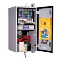
Overview of the Form 6 recloser control and its documentation.

Acceptance and Initial Inspection

Procedures for inspecting the recloser control upon receipt.

Control Battery Storage and Charging

Recommendations for storing and charging the control's 24 VDC battery.

Battery Replacement and Disposal

Guidance on battery life, replacement, and responsible disposal.

Operation Upon Loss of AC Power

FORM 6 RECLOSER CONTROL DESCRIPTION

Description

Overview of the recloser control's functionality, analysis, and metering capabilities.

Theory of Operation

Explanation of the control's functional block diagram and current sensing principles.

Control Panel Overview

Control Front Panel

Description of the control's front panel layout and indicators.

Front Panel Text Messaging

How to access and program text messages displayed on the LCD.

Programming Panel

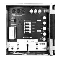
Details on the programming panel layout and function keys.

LCD Display

Description of the LCD display and its navigation buttons.

Status Indicators and Panel Controls

Status Indicator LEDs

Explanation of the status LEDs on the control's operator panel.

Operating Panel Controls

Description of front panel pushbuttons and switches.

Key Control Features

Control Security

Customer-programmable security codes for control access.

Protection Profiles

Four profiles for specifying control operation parameters.

Time Current Curves

Availability and customization of time-current curves for protection.

Sequence Coordination

Feature to prevent nuisance tripping through trip coordination.

Control Functions and Data

Metering

Provides instantaneous and demand metering with programmable intervals.

Event Recorder

Capability to perform Sequence of Events time-stamping.

Recloser Duty Monitor

Monitors and records duty for each phase in non-volatile memory.

Discrete SCADA Communications

Configurable output status and input control contacts.

Advanced Control Functions

Removable Inserts

Customization of protection requirements using inserts.

Idea Workbench

Access to inputs, variables, and alarms for user customization.

Sync Check

Permissive system to qualify close signals with voltage/frequency verification.

Manual Close Delay

Programmable delay for manual close operations.

Communications and Information

Communication Ports

Details on back panel communication ports and front panel data port.

Communication Protocols

Available protocols for the recloser control.

Ethernet Communications

Network application using Ethernet for DNP3 and ProView protocols.

Control Back Panel

Description of the back panel connections and ports.

INSTALLATION PROCEDURE

Initial Programming Prior to Installation

Critical steps for programming settings before energizing the recloser.

Control; Recloser Compatibility

Information on compatible Kyle reclosers and interface requirements.

Control Mounting and Locking

Mounting the Control

Guidelines for physically mounting the recloser control.

Locking the Control

Methods for securing the control cabinet with a padlock.

Cable and Grounding Procedures

Control Cable

Information on control cable fabrication, support, and length limits.

Grounding the Control

Methods and importance of grounding the control and recloser.

Grounding with a Local Supply Voltage Transformer

Recommended grounding for local supply transformers.

Remote Grounding Method

Recommended grounding for remote supply transformers.

Customer Power Connections

Customer Connections for AC Power

How to connect AC power to the control's terminal blocks.

Power Supply; Battery Charger Board

Details on the board that manages AC input and battery charging.

Supervisory Connections and Protection

Standard Default Supervisory Input Control and Output Status Contacts

Default configurations for supervisory I/O contacts.

Shielding and Surge Protection of Supervisory Cables

Protecting supervisory cables with shielding and MOVs.

Rear Panel Communication Ports

Rear Panel RS-232 Communication Port Pin Assignments

Pinout details for the rear panel RS-232 port.

Service Procedures

Before Placing the Control and the Recloser into Service

Essential steps before energizing the control and recloser.

ACCESSORIES

Low Voltage Closing

Accessories for low voltage closing power.

Internal Voltage Sensing

Accessory for Type NOVA reclosers with internal voltage sensing.

Incoming Power Receptacles

Options for plugging power cables into the control.

Option Accessories

Discrete Interface Board (DIF) Option Accessory

Provides additional configurable input/output contacts.

Radio Mounting Accessory

Accessory for mounting and powering radio equipment.

Communication Board Accessories

RS485 Serial Communication Card

Card for asynchronous serial communications.

Fiber-Optic Based Serial Communication Card

Card for serial communications via multi-mode fiber.

Ethernet Communication Cards

Cards for Ethernet network connectivity.

TESTING

Testing an Installed Control

Initial operational tests for an installed control.

Control Removal and Testing Procedures

Remove the Control from Service

Procedures for safely disconnecting the control for testing.

Preliminary Testing with No AC Available

Steps for testing the control using battery power only.

Testing with Type MET Tester

Using the MET Tester for specific control functions.

Recloser Electrical Closing Methods

Manual Closing - Solenoid-Operated Reclosers

Steps for manually closing solenoid-operated reclosers.

Battery Test and Charging Procedures

Test Procedure for Installed Battery

Steps for testing the installed control's battery.

Test Procedure for Uninstalled Battery

Procedures for bench testing a removed battery.

Control Return to Service and VTC Interface

Return the Control to Service

Steps to put the control back into service after testing.

RECLOSER VTC INTERFACE

Information on VTC-ready controls for NOVA reclosers.

CONTROL VTC INTERFACE

Details on VTC interface and retrofit kits for compatibility.

ADDITIONAL INFORMATION

Replacement Kits

Information on ordering replacement kits for the control.

Factory-Authorized Service Centers

Locations for maintenance, repair, and testing services.

Factory Maintenance Classes

Training courses offered for the recloser control.

Type MET Recloser Control Tester

Information on a video program for tester operation.

Related product manuals