Customer Connections for AC Power
Input power to the Form 6 pole-mount recloser control is
connected to terminal block TB7 for single-phase power or
TB8 for three-phase power.
See Figures 15, 17, and 19. For single-phase incoming
voltage supply for 120 VAC or 240 VAC, connect to TB7 as
shown in Figure 15. For three-phase incoming voltage sup-
ply, the user should supply and connect to TB8 as show in
Figure 17. For 240 Volt, 3-wire transformer connection
refer to Figure 19. Refer to Accessory section for 120 VAC
or 240 VAC low voltage closing.
Input power is required:
• To power the control
• To provide voltage and power metering
• To power the thermostatically controlled heater
• For the low voltage closing accessory
• For the convenience outlet accessory
Power Supply / Battery Charger Board
Incoming AC power is routed to the Power Supply / Battery
Charger Board designed to accept either 120 VAC or 240 VAC
through a selector switch located directly on the board (Figure
13). The battery charger includes a temperature-compensated
design to optimally charge the control battery. The power
supply / battery charger board also includes an auxiliary power
supply for connection to communication equipment (radios,
modems, etc.). The auxiliary power supply is rated 28 VDC, 65
Watts peak. A separate 28 VDC to 13.8 VDC power supply
accessory is available for communication equipment rated for
13.8 VDC. Some additional features are as follows:
• Positive LED indicator for power supply presence.
• Selectable 120/240 VAC switch for adapting to multiple
transformer connections. The selector switch is factory-
set based upon each customer order.
• Self-protective fuse (5 amp, 250 VAC).
• 28 VDC whetting voltage for I/O contact inputs.
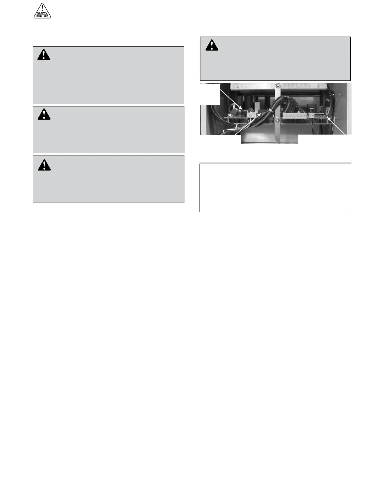
Terminal Blocks
Two terminal blocks are used for connection to the Form 6
recloser control. Both terminal blocks are fit for a #6 screw
which can allow a maximum ring size for a #10 AWG for
metering.
Terminal Block TB7 provides power to the Form 6 recloser
control and is directly connected to the power supply
circuit board. Terminal Block TB8 is used to connect
sensing transformer voltage. The wiring of the transformers
should follow the application illustrations per Figures 16,
17, 18, and 19.
Default factory wiring includes connection of two wires
from Power Supply Terminal Block TB7 to the Metering
Terminal Block TB8. See Figure 14.
Figure 18 shows customer connections for TB8, 120 VAC
Delta Connection.
The wiring from TB7-3 to TB8-3 and from TB7-5 to TB8-4
connects the metering B phase to the control. If the
incoming power supply voltage is different, the B phase
power supply input must be moved to the appropriate
location. See Figure 16.
For A phase incoming power, connect to TB8-1.
For C phase incoming power, connect to TB8-5.
Note: Terminal Block positions TB7-3 and TB7-4 are factory-
jumpered together.
Note: Terminal Block positions TB7-5 and TB7-6 are factory-
jumpered together.
Power Connections
The transformer required for power should be a minimum
of 5 kVA for low-voltage AC closing reclosers and 1 kVA for
high voltage AC closing reclosers and control-powered
NOVA reclosers.
S280-70-3
21
CAUTION: Equipment misoperation. Verify that
the 120/240 VAC selector switch is correctly set
for incoming voltage. Failure to comply may cause
misoperation (unintentional operation) of the control
and/or equipment damage resulting in personal injury.
T278.0
IMPORTANT: Prior to energizing the control, the selector
switch must be set as follows:
• For 120 VAC incoming power, the selector switch
must be set to the 115V position.
• For 240 VAC incoming power, the selector switch
must be set to the 230V position.
Figure 13.
Power Supply / Battery Charger Board.
AC
Power
Fuse
Power Supply Board
Selector Switch
CAUTION: Equipment damage. Do not drill
connection holes into the top of the cabinet.
Connection holes in the top of the cabinet will allow
moisture to seep into the control and damage the
components or cause control misoperation. Failure to
comply will void the control’s factory warranty. T249.0
DANGER: Hazardous voltage. Do not connect
potential transformer low-voltage secondaries to
the control through cables or other wiring until the unit is
installed in the field. Transformer high-voltage primary
windings will become live when 120V AC is applied to
the control from an alternate source if the transformer
secondary is connected. Failure to comply may result in
severe personal injury or death. T371.1
WARNING: Hazardous voltage. Before applying
power to the control, confirm that male pins of
the input power receptacle are electrically insulated to
prevent unintentional contact with 120V AC voltage.
Failure to do so may result in severe personal injury or
death. T372.0
 Loading...