Remove the Control from Service
1. Enable GND TRIP BLOCKED to disable the ground
element.
Note: This prevents the control from tripping on imbalance
as the control cable is connected and disconnected.
A. Press the CHANGE button on the Operator Panel to
enter the CHANGE mode.
B. Press the GND TRIP BLOCKED button within ten
seconds after entering the CHANGE mode.
Note: If the GND TRIP BLOCK button is not pressed
within ten seconds, the function is not activated.
2. Disconnect the 24V control battery.
3. Disconnect control cable from control.
4. Remove control AC sensing and power connections
from the control.
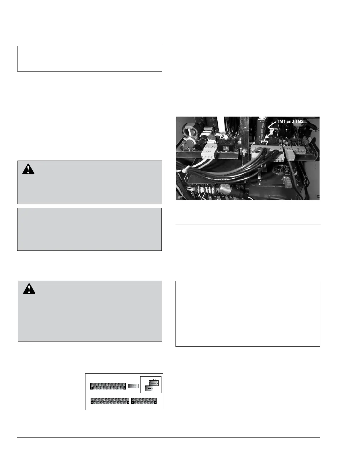
5. Remove any control input and status output wiring
from TB1, TB3, and TB4 (Figure 41).
6.
Disconnect any serial
communications ports
and IRIG-B timing con-
nections (Figure 41).
7. Disconnect the
ground from the con-
trol.
8. Carefully transport the
control to a suitable
service facility.
Preliminary Testing with No AC
Available
If the Form 6 control is not in service and requires
energization for preliminary testing, it can be powered up
with battery power only.
Note: Controls with expanded memory require battery voltage
to be 23VDC minimum.
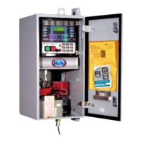
1. Open the rear door of the Form 6 pole-mount control
cabinet and locate terminals TM1 and TM2 on the
power supply circuit board (Figure 42).
2. Momentarily jumper terminals TM1 and TM2 together.
(The control will power up.)
3. To power down the Form 6 control, unplug the battery
(disconnect the black/red battery connector).
4. Perform a battery charging cycle. Refer to Battery
Charging in the Battery Test and Charging
Procedures section of these instructions.
Testing with Type MET Tester
The Type MET electronic recloser control tester (Figure 43)
is used for testing the following functions of the Form 6
recloser control:
• Overcurrent Timing
• Reclose Time
• Operating Sequence
• Reset Time
• Minimum Trip Current
• High Current Trip and Lockout
Form 6 Microprocessor-Based Pole-mount Recloser Control Installation and Operation Instructions
46
TB1
1
2
3 57911 13 15 17 19
46 81012141618
CI1
CI2 CI3 SS1 CO1
CO2 CO3
CO4
CI4
CI1 CI2 CI3 SS1 CO1 CO2 CO3 CO4
TB3
1
3
579111315171921
CI5 CI6 CI7 CI8 CI9 CI10 CI11 CO5 CO6
TB4
2
46 81012141618
20
CI4 CI5 CI6 CI7 CI8 CI9 CI10 CI11 CO5
CO6
13
5
7911 13
CO7CO8
CO9CO10CO11
CO12
2
46 81012
CO7CO8 CO9CO10CO11CO12
J1-RS-232
IRIG-B
RS-485
RS-232 DTE
C + –
Figure 41.
Back view of top half of Form
6 pole-mount recloser control.
IMPORTANT: Disconnect switches for AC sensing and
power connections are necessary to isolate the Form 6
control for testing and servicing.
CAUTION: Hazardous voltage. Open CT sec-
ondaries can generate high voltages. Contact
with CT pins of the disconnected cable can cause elec-
tric shock and may result in personal injury. Open
recloser contacts and open disconnect switches before
disconnecting control cable. T204.3
CAUTION: Hazardous Voltage. Cable
conductors attached to controls will remain at 53
VDC and 120 VAC potential while connected to the
control. Contact with any pins at the end of the cable
directly or indirectly connected to a control can result in
personal injury or equipment damage. Disconnect
battery and external power sources in the control then
remove control cable at control end before disconnecting
from recloser end. T312.2
IMPORTANT: While the Form 6 control is powered in
this manner, the control battery is being continuously
discharged. When the battery voltage drops to 22V DC,
the control will automatically power down.
If the battery is left in a discharged condition, the
battery(s) will sustain permanent irreversible damage.
Therefore, a battery charging cycle should always be
performed after this procedure to bring the battery(s)
back up to full charge.
Figure 42.
Location of terminals TM1 and TM2 on the power
supply circuit board
CAUTION: Equipment misoperation. Disconnect all
control power sources prior to disconnecting or recon-
necting the control cable from the control. Failure to
comply can result in recloser misoperation at the time of
disconnection or reconnection of the control cable to the
control. T311.1
 Loading...