Communications
Communication Ports
The Form 6 control has two back panel communication
ports and a front panel configuration data port.
The front panel configuration data port is described in the
Operating Panel section of this manual.
There is one standard 9-pin RS-232 and one optional
communication port (RS-485, serial fiber, Ethernet wire or
fiber or both) on the back operator panel, as well as a
standard IRIG-B port for user time-syncing. See Figure 9.
Communication Protocols
Four communication protocols are available for the Form 6
recloser control:
• Modbus
• DNP3
• 2179
• IEC870-5-101
One communication protocol can be selected for either the
back panel RS-232 or the optional communication port.
All four protocols are selected and configured by the user
with the ProView Communications Workbench application
software.
Ethernet Communications
• ProView over TCP/IP
• DNP3 over TCP/IP
Ethernet connection allows for network application of the
Form 6 pole-mount control for both DNP3 and ProView
protocols. In addition, the front panel data port can
simultaneously communicate ProView to the PC.
Ethernet configuration is accomplished via ProView
interface software. Refer to Service Information S280-70-4
(ProView 4.X.X) or S280-70-21 (ProView 5.X.X) Form 6
Programming Guide , Section 4: Schemes, Communicating
with the Form 6 Control, for Ethernet Configuration
information.
When a communication protocol is selected for the optional
communication boards (serial fiber or the RS-485 serial
port), the RS-232 serial port is defaulted to ProView
interface software protocol.
DNP3 is factory-defaulted to the RS-232 port.
When a communication protocol is selected for the RS-232
serial port, the optional RS-485 or serial fiber optic board
is not active.
The RS-485 or fiber optic serial ports do not support
ProView interface software protocol.
The user can simultaneously communicate to the Form 6
control using both the front panel data port and the
appropriate back panel serial communication port (provided
the back panel RS-232 port or the Ethernet optional
communications board is not configured to be ProView
protocol).
Control Information
Control information includes firmware identification by
catalog number and name, date code, and ProView
release number. Control information is available through
the Settings menu on the front panel (Figure 4).
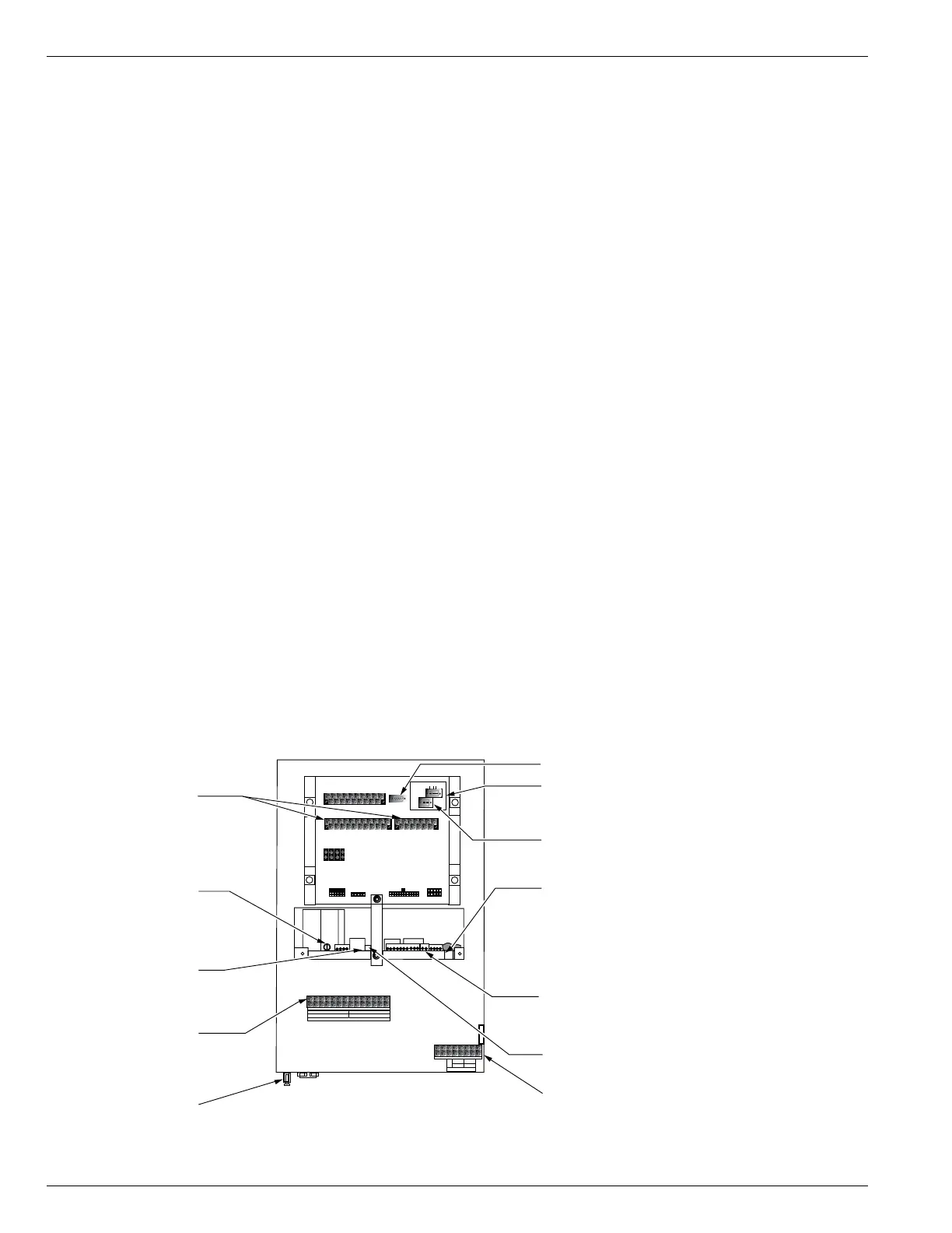
Control Back Panel
The control back panel is easily accessible through the
back door of the control cabinet (Figure 2) with readily
identifiable serial ports and connections (Figure 9).
Form 6 Microprocessor-Based Pole-mount Recloser Control Installation and Operation Instructions
14
TB1
1
2
35 7911 13 15 17 19
46 81012141618
CI1
CI2 CI3 SS1 CO1
CO2 CO3 CO4
CI4
CI1 CI2 CI3 SS1 CO1 CO2 CO3 CO4
TB3
1
3
579111315171921
CI5 CI6 CI7 CI8 CI9 CI10 CI11 CO5 CO6
TB4
2
46 81012141618
20
CI4 CI5 CI6 CI7 CI8 CI9 CI10 CI11 CO5
CO6
13
5
7911 13
CO7 CO8
CO9 CO10 CO11
CO12
2
46 81012
CO7 CO8 CO9 CO10 CO11 CO12
J1-RS-232
IRIG-B
RS-485
RS-232 DTE
Discrete Interface
Board (Accessory)
AC Power Fuse
RS-232 Serial Communication Port
Fiber Optic port, "ST" Type Connector (optional),
Ethernet Port, "MT-RJ" Fiber RJ45 Connector (optional)
Power Supply Board
AC Customer Connection
Terminal Block TB7
Grounding Terminal, One
External & One Internal
(#14 to #4 Stranded)
1
65
43
2
Power Supply LED
Power Connections
1
43
2
7
1211
109
8
Voltage Sensing
Customer Connection
Terminal Block TB8
120/240 VAC
Selector Switch
Battery Connector (2-position)
RS-485 Serial Communication Port (optional)
TB9
+
–
28 VDC
WHETTING VOLTAGE
P1
P2
P3
P4
VOLTAGE SENSING
53VDC CONTROL CABLE 28 VAC
1
2
3
45
1
2
3
45
23
22
21
20
19
11
10
9
87
18
17
16
15
14
6
5
4
32
13
1
24
12
1
2
3
45
3
1
3
1
3
4
2
4
24
1
2
C + –
IRIG-B Time Sync Connector
Figure 9.
Form 6 pole-mount recloser control back panel terminal block and communication port identification.
 Loading...