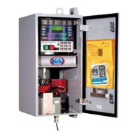
Discrete Interface Board (DIF)
Option Accessory
A Discrete Interface Board Option accessory provides
eight configurable input control contacts and eight
configurable output status contacts (Figure 36). The
ordering options include: Standard (3 inputs / 5 outputs) or
Additional (8 inputs / 8 outputs).
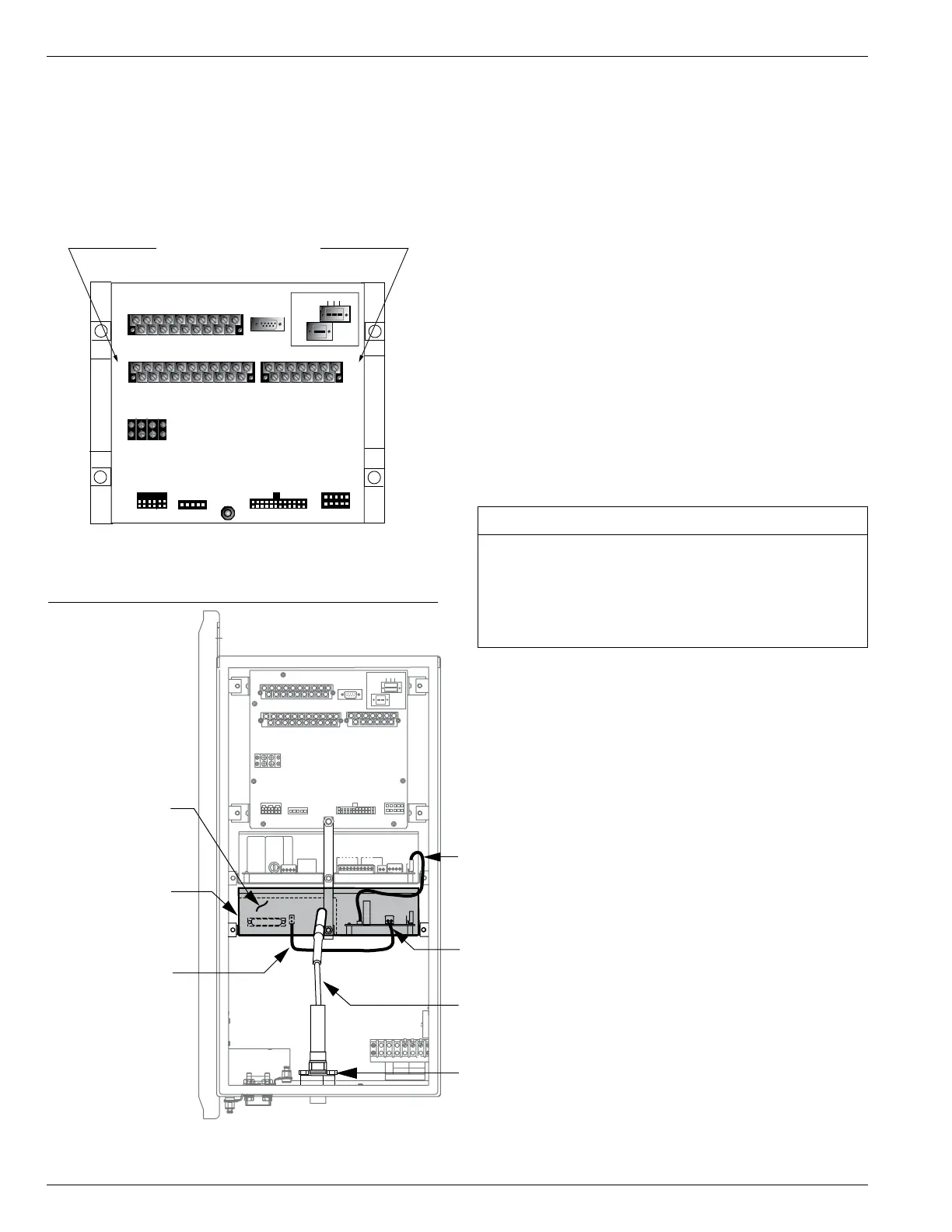
Radio Mounting Accessory
The radio mounting accessory (Figure 37) is powered from
a voltage regulated power supply factory-calibrated with
an output of 13.8 VDC.
The radio power supply input is fused by a 1 Amp in-line
fuse for a nominal voltage of 28 VDC. The output is 13.8
Vdc between P2-1 (+) and P2-2 (-) on the radio power sup-
ply circuit board with a maximum continuous watt rating of
17.25W @ 13.8 VDC.
Note: This output cannot be field-calibrated.
The radio will continue to operate during the loss of AC
power as long as power is supplied from the battery. The
power supply is designed to provide up to 40 Watts (peak)
and is fused to isolate any potential radio problems without
disturbing the protection system in the recloser control.
Refer to Table 11.
Contact your Cooper Power Systems representative for
any additional voltage requirements.
Form 6 Microprocessor-Based Pole-mount Recloser Control Installation and Operation Instructions
42
Radio-Mounting
Bracket
24 VDC to 13.8 VDC
Converter
Customer-Supplied
Power Leads
Radio Antenna
Cable (only
available with full
automation accessory)
Power Cable
Antenna Surge
Suppresser and
Connector (only
available with full
automation accessory)
Customer-Supplied
Radio
J1-RS-232
IRIG-B
RS-485
RS-232 DTE
TB9
+
–
28 VDC
WHETTING VOLTAGE
P1
P2
P3
P4
VOLTAGE SENSING
53VDC CONTROL CABLE 28 VAC
1
2
3
45
1
2
3
45
23
22
21
20
19
11
10
9
87
18
17
16
15
14
6
5
4
32
13
1
24
12
1
2
3
45
3
1
3
1
3
4
2
4
24
1
2
C + –
Figure 37.
Form 6 recloser control radio mounting accessory.
Description Catalog Number
Full Automation accessory
12 VDC radio provision ................ KME6-1774-3
(Radio and fiber-optic/RS232 interface not included)
Automation accessory (bracket only)
12 VDC provision ...................... KME6-1774-2
TABLE 11
Radio Mounting Accessories
TB1
1
2
3 57911 13 15 17 19
46 81012141618
CI1
CI2 CI3 SS1 CO1
CO2CO3
CO4
CI4
CI1 CI2 CI3 SS1 CO1 CO2CO3 CO4
TB3
1
3
579111315171921
CI5 CI6 CI7 CI8 CI9 CI10 CI11 CO5CO6
TB4
2
46 81012141618
20
CI4 CI5 CI6 CI7 CI8 CI9 CI10 CI11 CO5
CO6
13
5
7911 13
CO7CO8
CO9CO10CO11
CO12
2
46 81012
CO7CO8 CO9CO10CO11CO12
J1-RS-232
IRIG-B
RS-485
RS-232 DTE
TB9
+
–
28 VDC
WHETTING VOLTAGE
P1
P2
P3
P4
VOLTAGE SENSING
53VDC CONTROL CABLE 28 VAC
1
2
3
45
1
2
3
45
23
22
21
20
19
11
10
9
87
18
17
16
15
14
6
5
4
32
13
1
24
12
1
2
3
4 5
3
1
3
1
3
4
2
4
24
1
2
C + –
DIF Board Accessory
Figure 36.
Form 6 recloser control discrete interface board
accessory.
 Loading...