Testing an Installed Control
The following tests to determine initial operation of the
Form 6 pole-mount recloser control can be performed
while connected to an operating recloser.
Note: These are the only tests performed on an installed,
operating control.
1. Verify operating status of all indicator lights by pressing
and holding the LAMP TEST key for two seconds on
the programming panel (Figure 39).
2. Check the operational values for currents, voltages,
and other metering information.
Note: Scroll through the LCD display messages by pressing
the and cursor movement arrows underneath
the LCD display on the programming panel (Figure
35).
3. Test battery operation as follows:
Note: The battery test is blocked for 30 seconds upon
power up of the control.
Note: AC power can be either connected or disconnected
for battery test.
A. Press the MENU button on the front panel.
B. Using the down arrow key, navigate to the BATTERY
menu, and press ENTER.
C. Using the down arrow key, navigate to the TEST
BATTERY menu and press ENTER.
D. Press the F4 button to test the battery.
Note: This message will appear on the programming
panel LCD display: ----TESTING----
The battery test results will display in the battery
metering menu.
Note: Voltage should be between 25–31 VDC – with the
higher voltage at colder temperatures.
Under normal conditions, with AC connected and
a fully charged battery, the charging current
should be less than 20 mA.
With AC connected and a discharged battery, the
current range should be 20–450 mA.
With AC disconnected and the battery supplying
the load, current will read -400 to -600 mA
depending on accessories connected.
4. Verify the Control OK LED is illuminated on the control
operator panel (Figure 40). This indicates the presence
of AC power.
Note: The control includes a Power Save feature that will
turn off the backlit LCD display and all LEDs if no
front panel keypad is pressed within ten minutes.
Pressing the LAMP TEST key will reactivate the dis-
play and active LEDs.
All other tests described in this TESTING section require
the Form 6 pole-mount recloser control to be removed
from service, connected to a bypassed recloser, or tested
at a location where the proper testing equipment is avail-
able.
S280-70-3
45
TESTING
CAUTION: Equipment misoperation. Do not
connect this control to an energized recloser until
all control settings have been properly programmed and
verified. Refer to the programming information for this
control. Failure to comply can result in control and
recloser misoperation, equipment damage, and personal
injury. G110.3
IMPORTANT: The Form 6 control can be taken out of
service for testing and placed back into service without
de-energizing its recloser and interrupting the system.
However, during the time the control is out of service,
the recloser is inoperative.
CONTROL POWER
CONTROL OK
CONTROL LOCKOUT
RECLOSER OPEN
RECLOSER CLOSED
A PHASE FAULT
B PHASE FAULT
C PHASE FAULT
GROUND FAULT
SENSITIVE GND
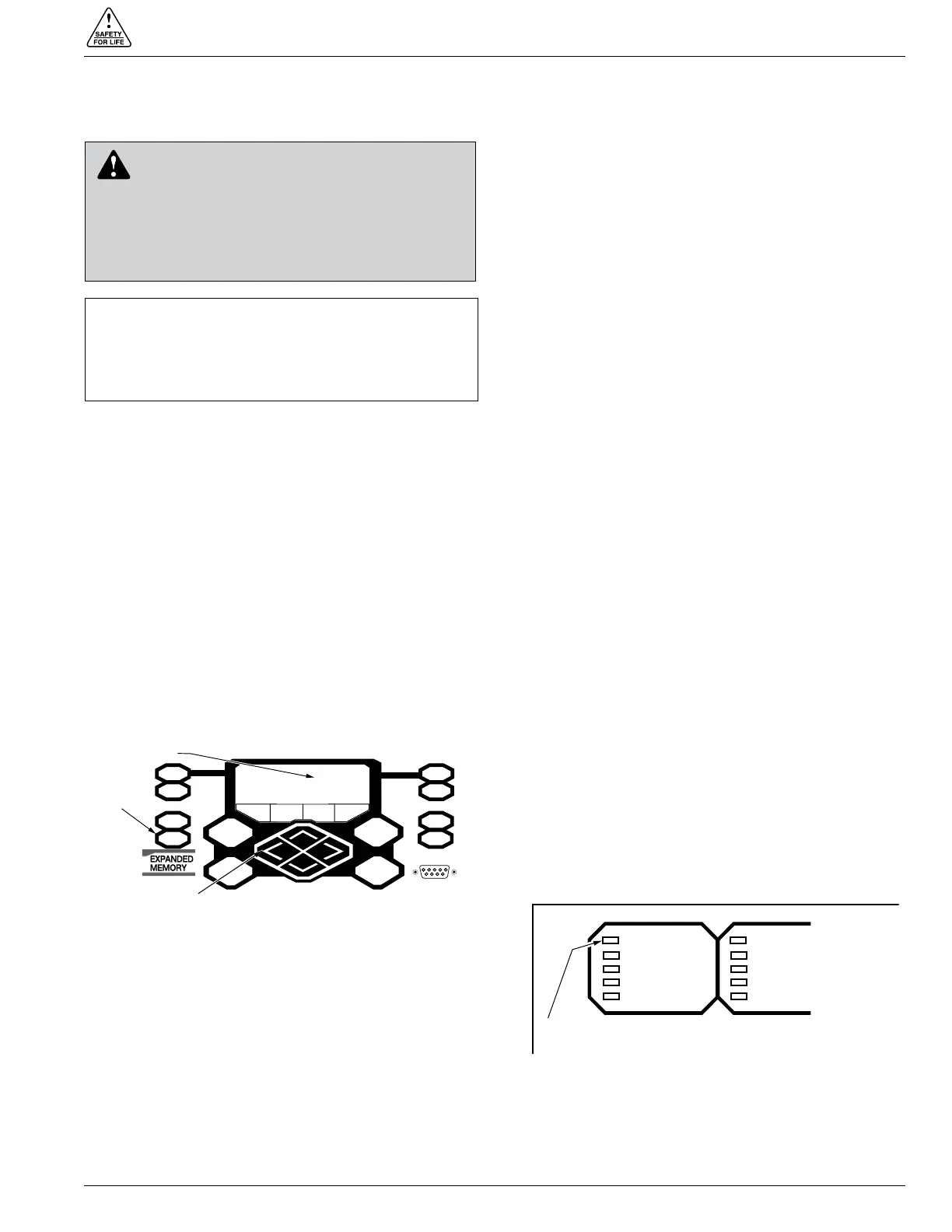
Control OK LED
Figure 40.
Control OK LED.
METERING
RESET
TARGETS
EVENTS
LAMP TEST
MENU
ENTER
+
—
SETTINGS
OPER
COUNTER
ALARMS
CHANGE
F1 F2 F3 F4
RS-232 DATA PORT
LCD Display
LAMP TEST Key
Cursor Movement
Arrows
Figure 39.
Lamp Test button, LCD display, and cursor movement
arrows.
 Loading...