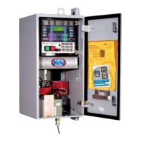
Control Cable
The control cable is fabricated with connectors which mate
with the female receptacle of the recloser on one end, and
the male receptacle of the control or junction box on the
other end.
Note: The control cable must be supported along its length to
prevent repeated movement due to wind or other outside
forces which can damage the cable.
Limits on control cable lengths are determined by the
recloser type and the distance between the control and
recloser: See Table 3 for available Form 6 recloser control
cable lengths for Kyle reclosers.
Grounding the Control
The control cabinet must be grounded. A grounding
connector on the underside of the cabinet will accommodate
No. 14 solid through No. 4 stranded conductors.
Suggested methods for grounding the control and recloser
are shown in Figures 11 and 12.
Figure 11 illustrates grounding methods for 4-wire multi-
grounded systems with local supply voltage transformer.
Figure 12 illustrates grounding methods for 4-wire multi-
grounded systems with remote supply voltage transformer.
For effective surge protection, all control and power
conductors for the Form 6 control must be routed parallel
to a corresponding ground path. For example, the AC
power supply for the control should be parallel to and equal
in length to the transformer ground path. The control cable
should be parallel to and routed close to the recloser
ground path.
Form 6 Microprocessor-Based Pole-mount Recloser Control Installation and Operation Instructions
18
WARNING: Hazardous voltage. Recloser and
control must be solidly grounded. Follow all
locally approved procedures and safety practices when
grounding this equipment. Improper grounding can
result in contact with high voltage, which will cause
death or severe personal injury. G115.1
TABLE 3
Available Form 6 Control Cable Lengths for Kyle Reclosers
Recloser Type Gauge Length (Meters) Length (Feet)
WE, WVE27, WVE38X, VWE, VWVE27, VWVE38X;
Auxiliary-Powered NOVA15, NOVA27, and NOVA38 18 24.1 (maximum) 79 (maximum)
16 24.4 to 38 80 to 125
14 38.4 to 61 126 to 200
VSA12, VSA12B, VSA16, VSA20,
VSA20A, VSO12, VSO16 18 3.4 to 6 11 to 20
16 6.4 to 10.7 21 to 35
14 11 to 15.25 36 to 50
Control-Powered NOVA15,NOVA27, and NOVA38 16 3.4 to 38 11 to 125
WARNING: Hazardous voltage. Recloser and
control must be solidly grounded. Follow all
approved procedures and safety practices when
grounding this equipment. Improper grounding can
result in contact with high voltage, which will cause
death or severe personal injury. G115.1
IMPORTANT: All external inputs to the Form 6 recloser
control must be routed within 8 inches of their
corresponding ground. During a surge, a potential of
approximately 1.5 kV per foot can develop in the
conductors. Differences between conductor and ground
path lengths can add additional stress to the control
components in the event of a power surge.

 Loading...