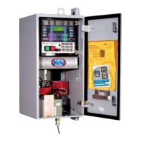
Battery Test and Charging
Procedures
Test Procedure for Installed Battery
Follow the procedure below to perform a battery test in the
Form 6 pole-mount control. The values in the test
procedures are based on testing at 25ºC (77ºF).
The condition of the Form 6 pole-mount control battery
can be determined by using the Battery Test function in the
BATTERY MENU. No external current/voltage meter is
necessary for testing.
Alarm Conditions:
• During a manual battery test a 5Ω, 55 watt resistor is
placed across the battery terminals for approximately
5 seconds. The Form 6 control measures the battery
voltage, if the voltage drops below 22.8 VDC for one
full second, the ALARM LED (battery alarm) is
illuminated.
• When the Form 6 pole-mount control is disconnected
from AC power and the control battery drops below 23.5
VDC for 60 seconds, the ALARM LED will illuminate. If
the battery voltage continues to decay and drops below
22 VDC, the Form 6 control will shut down.
Note: The battery test is blocked for 30 seconds upon power
up of the control.
Note: AC power can be either connected or disconnected for
battery test.
Note: If the battery voltage drops below 19V, the battery must
be charged by the external battery charger
KA43ME7001.
1. Press the MENU button on the front panel.
2. Using the down arrow key, navigate to the BATTERY
menu and press ENTER.
3. Using the down arrow key, navigate to the TEST
BATTERY menu and press ENTER.
4. Press the F4 button to test the battery. The battery test
results will display in the battery metering menu.
Note: Voltage should be between 25–31 VDC with the
higher voltage at colder temperatures.
Under normal conditions, with AC connected and a
fully charged battery, the charging current should be
less than 20 mA.
With AC connected and a discharged battery, the
current range should be between 20 and less than
450 mA. Current of 450 mA or greater indicates a
problem with the charging circuit on the pole-mount
power supply.
With AC disconnected and the battery supplying the
load, current will read -400 to -600 mA depending on
connected accessories.
Test Procedure for Uninstalled Battery
The entire process should be conducted in a clean environ-
ment, such as a repair shop.
Refer to Table 13 and follow this procedure to perform a
bench test on a control battery in a service shop:
1. Remove the control from service. Refer to Remove the
Control from Service procedure within the Testing
section of this manual.
2. Remove the battery from the control and carefully
transport it to a suitable service facility.
3. Measure battery voltage.
4. Apply test load and measure battery voltage after 5
seconds of load to determine voltage drop. Refer to
Table 13 for Bench Test Load Condition.
5. Remove test load.
If the battery fails the test or is at least four years old, it
should be replaced. Refer to Table 13 for battery catalog
part numbers.
Form 6 Microprocessor-Based Pole-mount Recloser Control Installation and Operation Instructions
50
TABLE 13
Control Battery Bench Testing and Replacement Information
Bench Acceptable
Battery Test Load Voltage Drop
Catalog Amp/ Condition at End of
Control Type Part # Voltage Type Hour for 5 sec. Test Load
Form 6 Pole-mount (standard capacity) KME4-215 24v Lead 8 5
Ω
3v
Acid 55 watt or less
Form 6 Pole-mount (high capacity) KME5-134-1 24v Lead 13 5
Ω
2v
(two Acid 55 watt or less
12v
batteries)

 Loading...