Description
The Form 6 pole-mount microprocessor-based recloser
control includes extensive system protection functionality,
including phase, ground, and negative sequence overcurrent
protection, over/underfrequency, and voltage protection,
directionality, sensitive ground fault, and sync check.
Analysis tools include fault locating, event recording, TCC
Editor II, Idea Workbench, Data Profiler, and oscillography
functions, including oscillography replay.
Metering functions include demand and instantaneous
current on a per-phase basis, instantaneous voltage and
power factor on a per-phase basis, and power (real,
reactive, apparent) on a per phase or total basis.
Symmetrical components for both voltage and current are
displayed along with kilowatt-hours for energy metering.
Harmonics from the 2nd to the 15th harmonic are also
included.
The front panel LCD display is used to configure the
operating settings for the control. It is also used to display
metering, counter information, control parameters, reset
alarms, and provide diagnostic information.
Control parameters can also be programmed via a personal
computer connected to the control through the front panel
RS-232 port. Control programming, interrogation, and
operations are performed with Form 6 ProView interface
software on a personal computer.
ProView interface program software includes additional
functions used to create and graphically display Time
Current Curves and provides the Idea Workbench for
configuring user-selected inputs and outputs, configurable
event and alarm data, and selectable communication
points for serial communication.
The control operates on 50 and 60 Hz systems.
The control can be configured, by the factory or by the
user, for a wide variety of applications. If user requirements
change, the control functions can be modified to meet the
new requirements.
The control is accessible from both the front and back of
the cabinet (Figure 2).
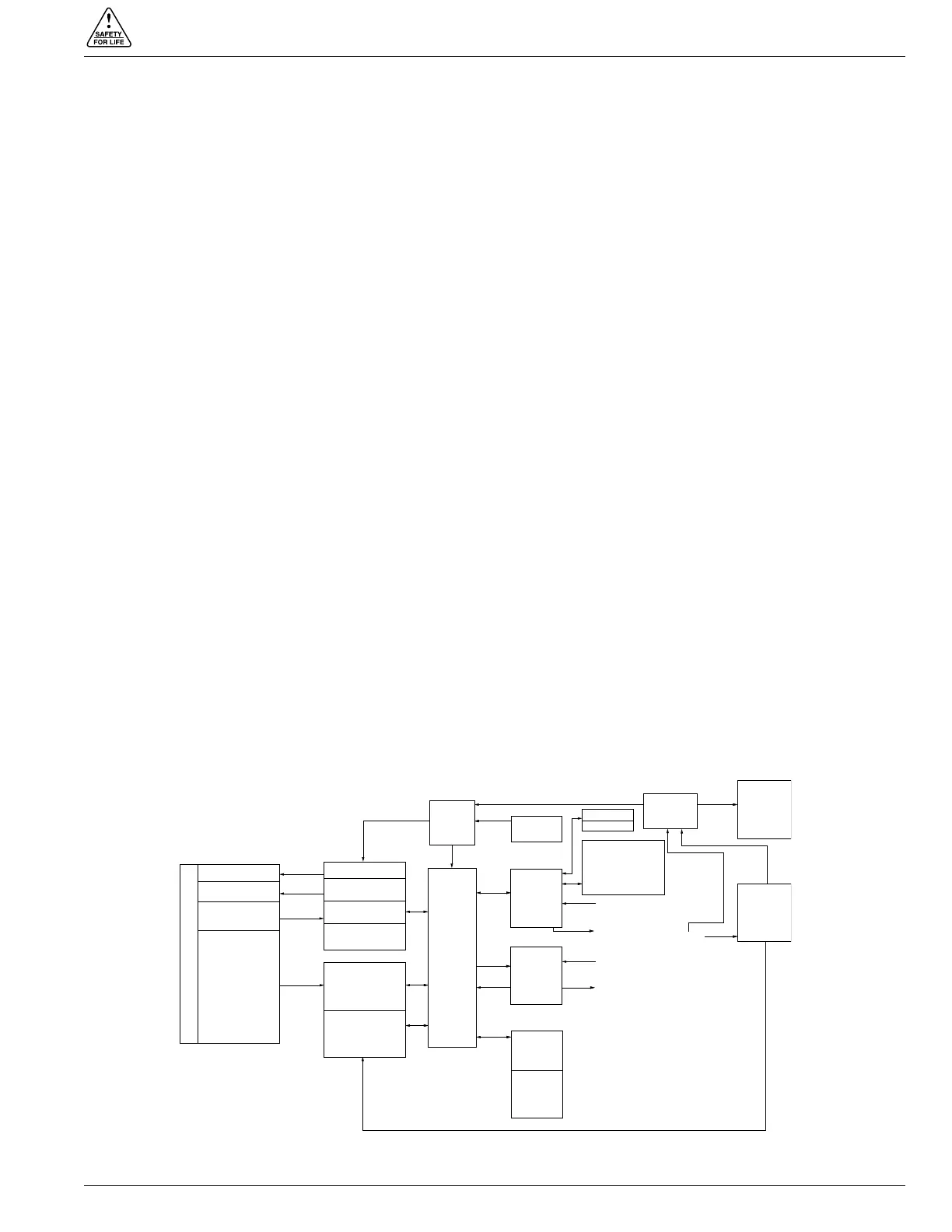
Theory of Operation
A functional block diagram of the Form 6 recloser control
is shown in Figure 3. Current sensing is provided by three
current transformers located in the recloser and interfaced
to the Form 6 recloser control via the control cable. This
cable also supplies Trip, Close, and Recloser status, and
connects to the Recloser Interface (RIF) module to provide
isolation for reliable operation. Voltages for metering are
connected to the analog input module through terminal
block TB8.
Line current flowing through the recloser is converted by
the CPU module to a digital signal suitable for metering and
fault current calculations. Data sampling occurs at a rate of
64 times per cycle. The CPU contains a data acquisition
section that uses the acquired samples to compute the
fundamental currents and voltage for use in overcurrent,
under/overvoltage, and under/overfrequency protection,
as well as currents and voltages for metering functions.
The current for overcurrent protection is calculated on a
sub-cycle basis; it includes only the fundamental and DC
component.
When the phase or ground current exceeds its programmed
minimum-trip value and associated time-current-curve
(TCC) timing, the control initiates the programmed sequence
of recloser tripping and reclosing operations via the CPU
and RIF modules. If the fault is temporary, the control
ceases to command recloser operations after a successful
reclose, and the control resets to the start of its operating
S280-70-3
5
TRIP SOLENOID
CLOSE SOLENOID
A Ø CT
B Ø CT
C Ø CT
OPEN / CLOSE
SWITCHES
CT COMMON
RECLOSER
POWER
BATTERY
INTERCON-
NECTION
BOARD
CPU
I/O
FRONT
PANEL
RS-232
(PROVIEW
PROTOCOL
ONLY)
TB7
TERMINAL
BLOCK
120/VAC
OUTLET
DUPLEX
ACCESSORY
TB8
TERMINAL
BLOCK
SENSING
VOLTAGE
INPUTS
3 inputs
USER
CONNECTIONS
5 outputs
8 inputs
USER
CONNECTIONS
8 outputs
POWER
CONNECTIONS
120/240
MATCHING
TRANSFORMERS
AND SIGNAL
CONDITIONING
ANALOG INPUT
RIF
OPTICAL
ISOLATION
OPTICAL
ISOLATION
OPTICAL
ISOLATION
OPTICAL
ISOLATION
RS-232
IRIG-B
COMMUNICATIONS
BOARD ACCY
•RS-485
•FIBER-OPTIC
•ETHERNET
Figure 3.
Form 6 pole-mount recloser control operational flow diagram.
FORM 6 RECLOSER CONTROL DESCRIPTION
 Loading...