Form 6 Microprocessor-Based Pole-mount Recloser Control Installation and Operation Instructions
44
The Ethernet communication card accessory is offered in 3
physical layer configurations (twisted pair and optical-fiber
options) as shown in Table 12.
Maximum link length is determined by the use of the par-
ticular physical layer implementation, and can be further
constrained by the actual network configuration. In case of
the 100Base-FX MT-RJ connector based implementation,
maximum link length in excess of 2000m can be achieved
with 62.5/125µm multi mode fiber. The fiber-optic link uses
1300nm wavelength, and can easily be interfaced to other
100Base-FX solutions (ST connector patch cord solution).
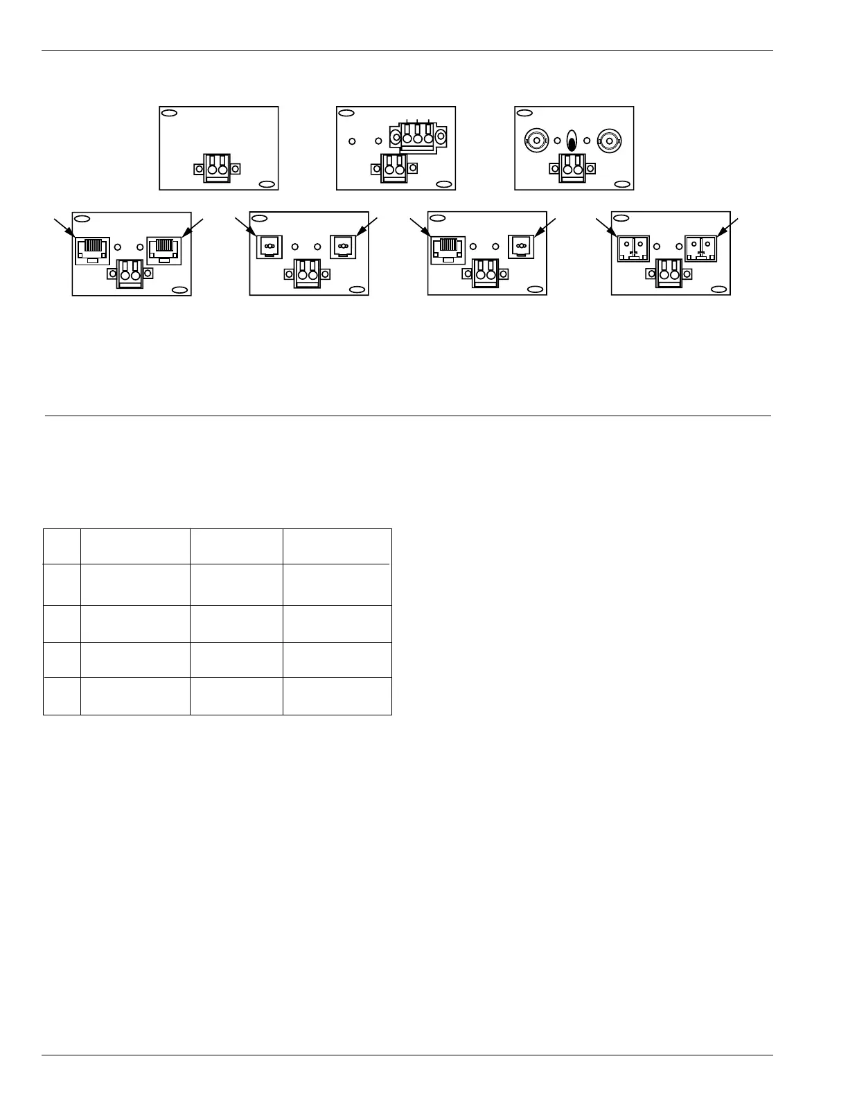
The Ethernet communication accessory card (Figure 38) is
equipped with two physical ports configured to act as pri-
mary and standby LAN connections. Availability of the
backup communication port enables creation of highly
redundant Ethernet networks thus increasing the overall
system reliability.
Note: Under normal network conditions, all communications
will be channeled through the primary port (#1, Figure
38), with the standby port either logically disabled, or
configured for fast automatic throw-over in case of the
primary Ethernet link failure. Refer to Service Information
S280-70-4 (ProView 4.X.X) or S280-70-21 (ProView
5.X.X) Form 6 Microprocessor-Based Recloser Control
Programming Guide for additional Ethernet accessory
configuration information.
TX
RX
NON-ECHO
Serial Fiber
Ethernet 100 Base-FX
Type 2
Ethernet 10/100 Base-T,
100 Base-FX
Type 3
Ethernet 10/100 Base-T
Type 1
#1
(No Communication Option)
IRIG-B
J5
RS-485 Communication
RS-485 C
-
+
RX
TX
#2
#1
#2 #1
IRIG-B
J5
J4 – ETHERNET – J3
2 1
IRIG-B
J5
J4 – ETHERNET – J3
2 1
IRIG-B
J5
J4 – ETHERNET – J3
2 1
IRIG-B
J5
IRIG-B
J5
Ethernet 100 Base-FX
Type 4
Default
Primary
Ethernet
#2 #1
IRIG-B
J5
J4 – ETHERNET – J3
2 1
Figure 38.
Back panel Ethernet and Communication options.
Card Output Communication
Type Configurations Connectors Speed
1 10/100 Base-T 2 * RJ-45 10 / 100MBps
(auto switching)
2 100 Base-FX 2 * MT-RJ 100MBps
(multi-mode fiber) (full duplex)
3 10/100 Base-T, RJ-45 + MT-RJ 10/100MBps
100 Base-FX and 100MBps
4 100 Base-FX, 2 * LC 100MBps
(single-mode fiber) (full duplex)
TABLE 12
Ethernet Communication Card Configurations