• Variable Autotransformer T1, 230 Volts, 20 Amps.
• Low-Voltage transformer T2 to simulate fault conditions.
Ratio and size will depend upon the maximum current
to be used. The recloser presents a low impedance to
the transformer, so secondary voltage must be only
high enough to force the required current through the
secondary of the transformer and the recloser.
Note: An alternative method of providing the necessary
current through the transformer is shown in Figure
45.
• High-Voltage T3 to operate the closing solenoid.
The closing coil requirement is approximately 200 kVA
during the two-to-three cycle closing operation. The
solenoid coil operating voltage must be maintained at
the recloser bushings during the cycle interval the
closing coil is energized. This procedure is not used on
reclosers equipped with the low-voltage closing
accessory.
• Ammeter with a rating based on the level of test
current.
• Current-actuated timer.
Form 6 Microprocessor-Based Pole-mount Recloser Control Installation and Operation Instructions
48
3
6
4
T3
Y
H*
X
Z
VOLTAGE RATING OF
RECLOSER CLOSING
SOLENOID COIL
SENSING CTs (3)
CLOSING
SOLENOID
CONTACTOR
ROTARY
SOLENOID
MAIN
CONTACTS (S)
G*K*
A* B*
E* F*
TO
240 OR
480 VAC
SOURCE
TO
240 VAC
SOURCE
CLOSING
SOLENOID
COIL
TRIP
SOLENOID
CONTROL
CABLE RECEPTACLE
W
FORM 6
CONTROL
TO
AMMETER AND RELAY TO
OPERATE CYCLE COUNTER
OR OTHER TIMING DEVICE
AC POWER
VARIABLE
AUTOTRANSFORMER
240 VAC
20 AMPS
T2
1
2
5
J*
T1
*Indicates control cable receptacle pin/socket designation.
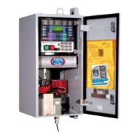
Figure 46.
Suggested test circuit for high voltage “shop-testing” solenoid-closing reclosers.
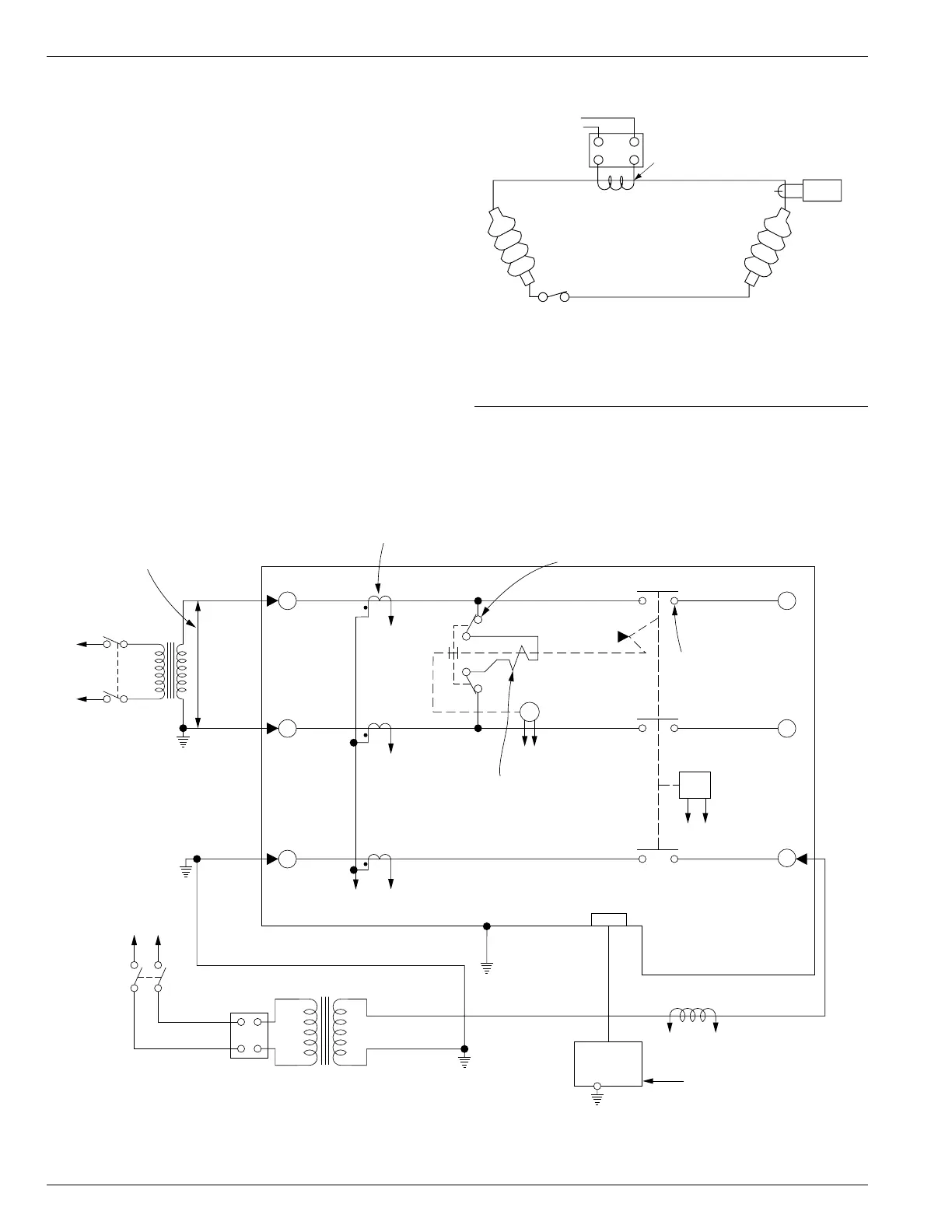
600:5
Recloser
BCT ON 600:5 Tap
Note: This test circuit
can apply over
800 Amps to the
recloser.
Note: Use at least 2/0
cable between
bushings.
2
1
115Vac
Variable
Autotransformer
(10 Amp)
Clamp-On
Ammeter
Figure 45.
Alternate method of producing variable line current
(substitute for T2 and W-X circuit in Figures 46 and
47).