Page 4
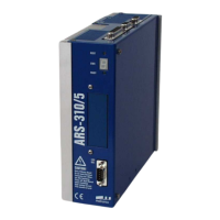
Product Manual “Servo Positioning Controller ARS-310/5(UL) ARS-310/10“ Version 2.3
Table of Contents:
1 GENERAL.........................................................................................................12
1.1 Documentation .......................................................................................12
1.2 Scope of supply......................................................................................13
2 SAFETY NOTES FOR ELECTRICAL DRIVES AND CONTROLLERS ...........14
2.1 Used symbols.........................................................................................14
2.2 General notes.........................................................................................14
2.3 Danger resulting from misuse.................................................................16
2.4 Safety notes............................................................................................16
2.4.1 General safety notes..................................................................16
2.4.2 Safety notes for assembly and maintenance .............................18
2.4.3 Protection against contact with electrical parts ..........................19
2.4.4 Protection against electrical shock by means of protective extra-
low voltage (PELV) ....................................................................20
2.4.5 Protection against dangerous movements.................................21
2.4.6 Protection against contact with hot parts ...................................21
2.4.7 Protection during handling and assembly ..................................22
2.5 Overload behaviour ................................................................................22
3 PRODUCT DESCRIPTION...............................................................................23
3.1 General...................................................................................................23
3.2 Power supply..........................................................................................25
3.2.1 AC supply ..................................................................................25
3.2.2 Power supply .............................................................................25
3.2.3 Mains fuse .................................................................................25
3.3 Brake chopper ........................................................................................25
3.4 Communication interfaces ......................................................................
26
3.4.1 RS232 interface .........................................................................
26
3.4.2 CAN-Bus....................................................................................26
3.4.3 Profibus......................................................................................26
3.4.4 I/O functions and device controller.............................................27
4 TECHNICAL DATA ..........................................................................................28
4.1 Operating and display elements .............................................................29
4.2 Supply [X9] .............................................................................................30
4.3 Motor connection [X6].............................................................................31
4.4 Motor feedback connection [X2] .............................................................31


 To Next Page
 Loading...