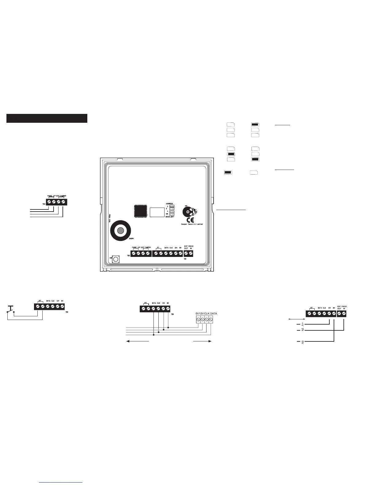
ADDRESS
Set the address of the keypad to 2, 3 or 4 by fitting the
jumper across the appropriate link. Leave the link off to set
the address to 1. No two keypads may have the same ad-
dress. Re-apply power after changing the address.
Wiring and Link Instructions
BACK LIGHT
Jumper not fitted (default) – Display
and keypad back lights are normally
off. When a key is pressed, the lights
will switch on at full brightness for 5
seconds.
Jumper fitted – Display and keypad
back lights are permanently on.
VOLUME CONTROL
Adjusts volume of key-
pad sounder.
To next key-
pad (max.4
keypads) or
expander.
Cooper Security recommend that you use 8-core 7/0.2 or 16/0.2
alarm cable for wiring keypads
You can connect the keypads in either a star or bus configuration. If
you are intending to use long cable runs then Cooper Security rec-
ommend that you use star wiring with no more than 200m of cable
per branch.
Keypad Wiring
Max. 200m to furthest keypad
External Panic Attack Button
Keypad PCB
Lock Switch
OR
Exit terminate button
(NO, push to make)
Lockswitch/ET button Wiring
Keypad 1 Keypad 2
Keypad 3 Keypad 4
Backlight ON Backlight OFF
If the panic attack does not contain a tamper
switch, link the pair of “EXT TAMPER” terminals.
Separately link both pairs of terminals if no panic
button is used.
To external PA
button
Control Unit
External Prox Wiring (9943 only)
Connect AX10 proximity reader to this terminal as shown.
50m Max.
RED
WHITE
BLACK
To AX10