9940, 9941 and 9943 Keypad
Installation Instructions
Introduction
The 9940, 9941 and 9943 keypads are designed to work
with 9853, 9851, 9752, 9751 and 9651 alarm system
control units. These keypads are a direct replacement for
the 9930, and offers the advantage of smaller size and
improved appearance.
The 9940 and 9943 keypada have a proximity tag reader
coil fi tted inside the case and can work with the same
proximity tags as the 934 proximity reader module. The
9941 has no detector coil fi tted. The 9943 can also be con-
nected to an external prox reader.
Installation
To install the keypad:
1. Ensure that all power (mains and battery) is removed
from the control panel.
2. If fi tted, remove the two screws located under the bot-
tom edge.
3. Separate the cover and back plate of the keypad.
4. Mount the keypad using M4/M3.5 screws. Mounting
and cable holes on the back plate are shown in Figure
1.
5. Connect all required wiring, as shown overleaf.
6. Use the links to set the address of the keypad and to
make any changes to standard operation.
7. Clip the cover onto the base and refi x the screws.
Note: The power LED is operated by the control unit
and may not be permanently lit. The control unit
shows a mains fail condition as an alert on the display.
9940 Mounting Locations
The 9940 and 9943 keypads contain a coil that detects
proximity tags employed by users to set and unset the
system. The coil works at a low radio frequency and has a
spherical detection area, which extends for approximately
120mm from the keypad. Proximity tags can be detected
through wood, brick, plaster, glass and plastic.
Excessive interference with external devices may lead to
poor read performance. Follow these simple guidelines to
prevent interference:
• Avoid mounting the keypad near magnetic devices,
such as motors, door releases, entry phones, loud-
speakers and PA systems.
• Avoid microwave devices such as ovens or detectors.
• Avoid mounting the keypad near large metal struc-
tures. Do not screw the keypad to a metal frame.
• Do not mount two readers back to back, even if there
is a wall between them. This also applies to the AX10
reader: do not mount the 9943 back to back with the
AX10.
• Warn users that holding a mobile phone in the same
hand as a tag may seriously affect the reading per-
formance.
If you are in doubt, test the operation of the keypad before
fi nally fi xing it in position.
Specifi cations
Sales number 9940EN, 9941EN or 9943EN
Security Grade 3
Environmental Class II
Operating temp. -10° to +55°C
Humidity 96% RH
Dimensions 115mm W, 115mm H, 24mm D
Weight 0.2 kg
Current consumption (9940) 30mA max continuous
backlight off
70mA max continuous
backlight on.
(9941) 20mA max continuous
backlight off
60mA max continuous
backlight on.
(9943) 30mA max continuous
backlight off.
70mA continuous backlight on.
Compliance EN51031-1
For further detail and
Declaration of Conformity
please go to www.
coopersecurity.co.uk.
CE Telefi cation
Inputs
Name Used For:
Panic External wired PA button.
Ext Tamper External tamper switch or
wiring.
ET Exit Terminate button.
Data, CLK Signal from control unit keypad
bus.
12V, 0V DC power supply.
Compatible Equipment
9853, 9851, 9752, 9751, 9651
This product conforms to the EMC (89/336/EEC) and LVD
(73/23/EEC) directives. For a full declarations of conform-
ity, please visit www.coopersecurity.co.uk.
© Cooper Security Limited 2007
Every effort has been made to ensure that this publication is
correct. However, neither the authors nor Cooper Security Lim-
ited accept any liability for loss or damage caused or alleged to
be caused directly or indirectly by this publication. The contents
of this publication are subject to change without notice.
Cooper Security Ltd.,
Security House,
Vantage Point Business Village,
Mitcheldean,
Gloucestershire,
GL17 0SZ
England
www.coopersecurity.co.uk
Product Support (UK) Tel: +44 (0)870 7575400
Available between:
08:15 and 17:00 Monday to Friday
Product Support Fax: +44 (0)1594 545401.
Part No. 11815702 issue 1.
4th December 2007
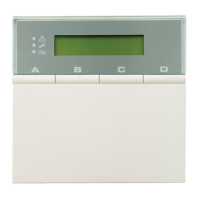
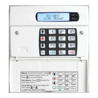
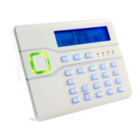
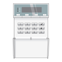
Controls and Displays
The 9940, 9941 and 9943 keypads have a two line by 20
character LCD display that shows “fi rst to alarm” informa-
tion, level status, and programming commands. In addition
there are three LEDs with the following functions:
Glows steadily when mains power is present.
Flashes when the system is working from bat-
tery backup.
Glows steadily when the system requires the
user to acknowledge an alert.
Glows steadily if:
a) A fault or tamper circuit is active while the
system is unset.
b) The system needs an engineer or remote
reset.
c) A telephone line fault is present.
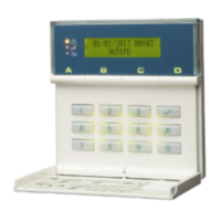
The 9940 keypad provides the following keys:
9 - 0 Used to key in access codes or select program-
ming commands.
Used to enter programming and setting/unset-
ting commands.
Used to set the system with individual zones
(including 24 hour zones) temporarily omitted.
ABCD Level or partition setting keys
In addition, some control units may support the Dual Key
Alarm function to allow users to start an alarm by pressing
the following pairs of keys:
1 + 3 Panic alarm
4 + 6 Medical assistance
7 + 9 Fire alarm
Figure 1: Cable entry (1), mounting holes (2), back tamper
aperture (3), sounder aperture (4)