47
Cable Tray Manual Cooper B-Line, Inc
Appendix Sheet 3
Example - NEC
®
Section 392.9(A)(1)
Width selection for cable tray containing 600 volt multiconductor cables, sizes #4/0 AWG and larger
only. Cable installation is limited to a single layer. The sum of the cable diameters (Sd) must be equal
to or less than the usable cable tray width.
Cable tray width is obtained as follows:
(D) (N) Multiply (D) x (N)
Item List List Cable List Number Subtotal of the
Number Cable Sizes Outside of Cables Sum of the Cables
Diameter Diameters (Sd)
1. 3/C - #500 kcmil 2.26 inches 4 9.04 inches
2. 3/C - #250 kcmil 1.76 inches 3 5.28 inches
3. 3/C - #4/0 AWG 1.55 inches 10 15.50 inches
The sum of the diameters (Sd) of all cables (Add Sds for items 1, 2, & 3.)
9.04 inches + 5.28 inches + 15.50 inches = 29.82 inches (Sd)
A cable tray with a usable width of 30 inches is required. For
a 10% increase in cost a 36 inch wide cable tray could be
purchased which would provide for some future cable additions.
Notes:
1. The cable sizes used in this example are a random selection.
2. Cables - copper conductors with cross linked polyethylene insulation and a PVC jacket.
(These cables could be ordered with or without an equipment grounding conductor.)
3. Total cable weight per foot for this installation.
61.4 lbs./ft. (without equipment grounding conductors)
69.9 lbs./ft. (with equipment grounding conductors)
This load can be supported by a load symbol "B" cable tray - 75 lbs./ft.
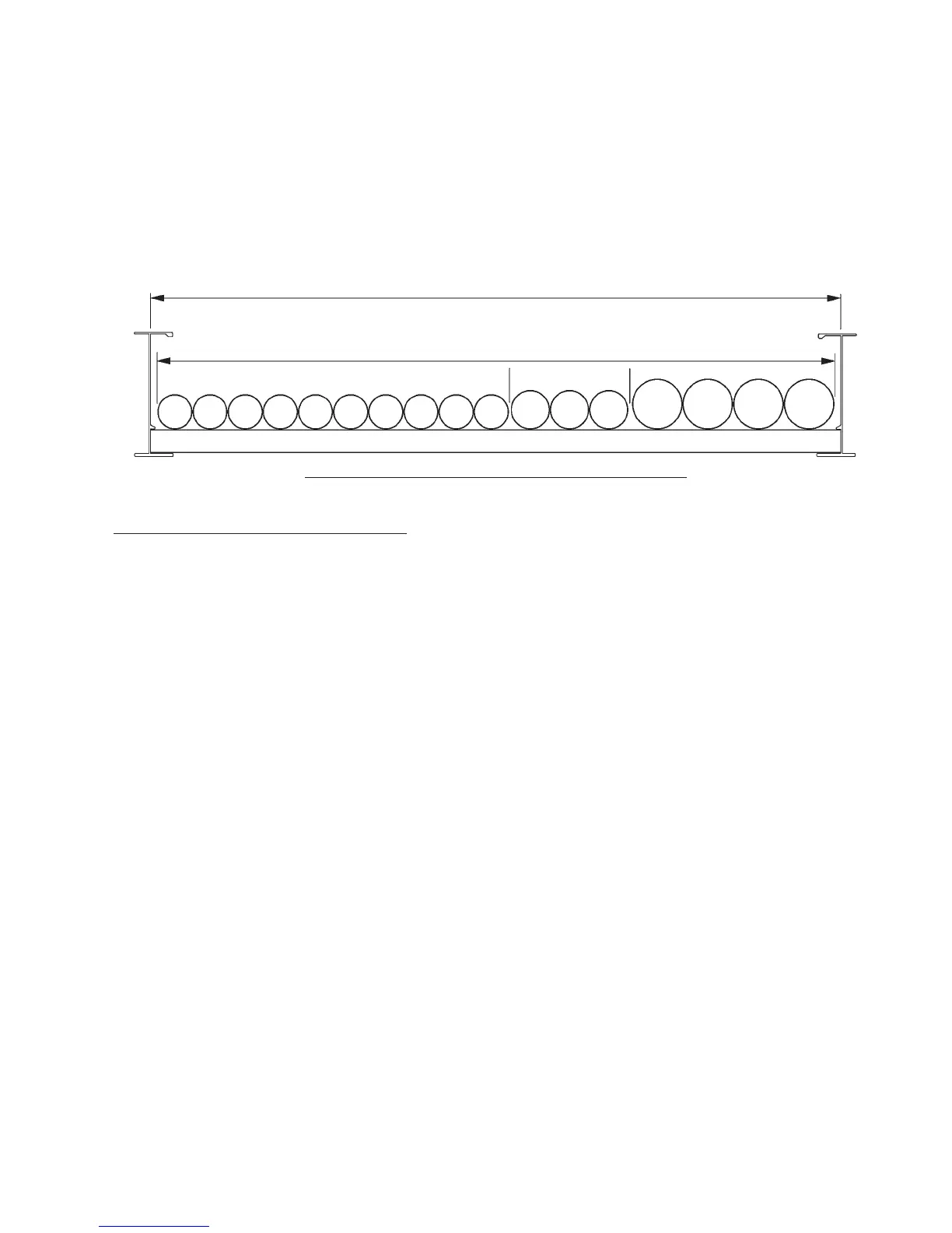
30" Usable Cable Tray Width
29.82" = Equals Cable Sd
Cross Section Of The Cables And The Cable Tray
3333333333
222
1111
 Loading...