Receiving
Inspection
Prior to shipment, the regulator is thoroughly tested
and inspected at the factory. Immediately upon receipt of
the regulator shipment, before unloading, a thorough
inspection should be made for damage, evidence of
rough handling or shortages. The position indicator,
junction box, arrester, radiators and bushings should
all be inspected for evidence of damage. Should this
initial inspection reveal evidence of rough handling,
damage, or shortages, it should be noted on the bill
of lading and a claim should immediately be made
with the carrier. Also, notify Cooper Power Systems,
2300 Badger Drive, Waukesha, Wisconsin 53188,
attention Service Manager.
Unloading
When an overhead crane is used for unloading, the
regulator must be lifted by means of a sling and
spreader bar utilizing the tank-mounted lifting lugs
which are shown in Figure 2. Do not lift the entire
unit with the lifting eyes on the cover. The lifting
eyes are only to be used to untank the internal assembly
which is attached to the cover.
Storing
If the regulator is not to be placed into immediate
use, it can be stored with minimal precautions. Store
the unit where the possibility of mechanical damage
is minimized.
Installation
Pre-Installation Inspection
Before connecting the regulator to the line, make the
following inspection:
1. Check oil sight gauge. Look for visible signs
of oil leakage.
2. Examine series arrester for damage. If damaged,
install a new arrester of same voltage rating.
3. Inspect porcelain bushings for damage or leaking
seals. If there is a suspicion that moisture has
entered unit, remove handhole cover and inspect
for evidence of moisture such as rust or water
tracks in oil. If moisture has entered that tank, dry
regulator and filter oil before putting unit in service.
See Table 1-5, page 1-12, for values that oil should
meet. Be sure to properly replace handhole cover.
4. Check position indicator for damage. When
cleaning the faceplate, do NOT use solvent or fuel.
5. If regulator has been stored for some time,
test dielectric strength of oil according to
Table 1-5, page 1-12.
6. Regulator may be energized at rated voltage (with
caution) and an operational check (see page 1-10)
can be performed. (This procedure is optional.)
7. A high-potential test may be done to ensure
adequate electrical clearances to ground. (This
procedure is optional.)
Receiving, Installation
and Maintenance
WARNING: The cover may fracture if the
cover-mounted lifting eyes are used to lift the
entire unit. Lift the entire unit only with tank-mounted
lifting lugs.
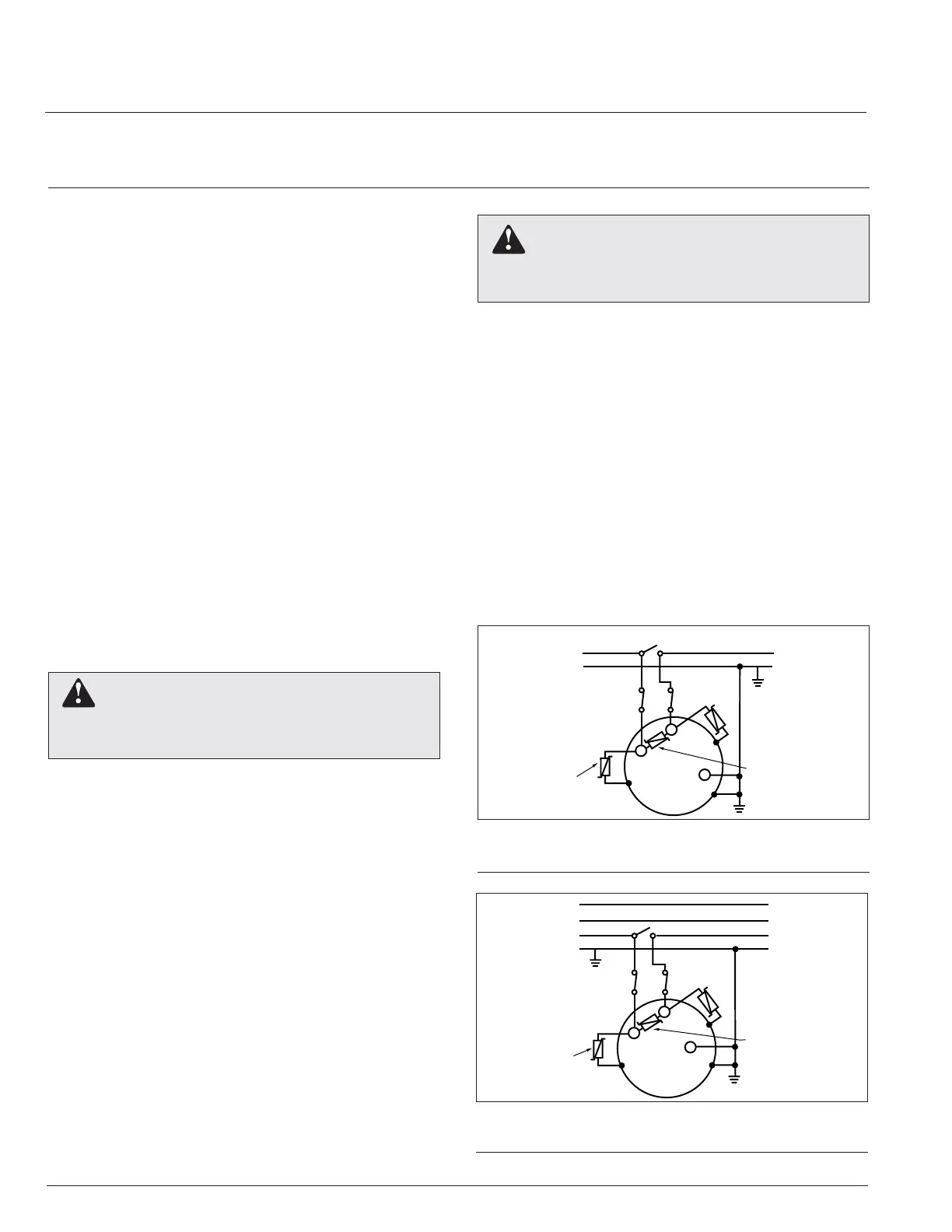
Figure 1-1.
Regulating a single-phase circuit

 Loading...

