EasyManua.ls Logo

Cooper MENVIER MF400 User Manual

Default Icon
12 pages
To Next Page IconTo Next Page
Page #1 background imageLoading...
Page #1 background image
PLEASE PASS THIS BOOKLET TO THE USER,
AFTER INSTALLATION KEEP WITH PANEL.
MENVIER FIRE SYSTEM
MF200/400 MF200-72/400-72
For service Tel:
please call:
Service agreement number
123
123
4
ZONE
POWER FAULT
SYSTEM FAULT
EARTH FAULT
ALARMS
SUPERVISOR
MODE
DISABLE M ODE
DISABLE TEST
TEST M ODE
REMOTE SIGNAL
DISABLE
POW ER
FIRE
FAULT
FAULT
SUPERVISOR M ODE SILE NCE/SOUND LAM P TEST/EXIT
SILE NCE BUZZERRESET
SELECT
SUPERVISOR
DISABLE
TEST
MF400
Cooper Lighting and Security Ltd.
Wheatley Hall Road, Doncaster, South Yorkshire, DN2 4NB, United Kingdom
Sales General Export
Tel: +44 (0)1302 - 303303 +44 (0)1302 - 321541 +44 (0)1302 - 303250
Fax: +44 (0)1302 - 367155 +44 (0)1302 - 303220 +44 (0)1302 - 303251
E-mail: sales@cooper-ls.com technical@cooper-ls.com export@cooper-ls.com
Lighting and Security
PINST MF4/V
www.cooper-ls.com
Question and Answer IconNeed help?

Do you have a question about the Cooper MENVIER MF400 and is the answer not in the manual?

Cooper MENVIER MF400 Specifications

General IconGeneral
BrandCooper
ModelMENVIER MF400
CategorySecurity System
LanguageEnglish

Summary

Panel Controls and Indicators

Keys

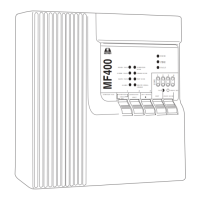
Explains the 5-key keyboard operation and the functions of keys 1, 2, and 3 in different modes.

Panel Operation

Supervisor Mode Operation

Describes operations within Supervisor Mode like Reset, Lamp Test/Exit, Silence/Sound Alarms, and Disable Mode.

Disable Mode

Explains how to disable/re-enable zones, alarm lines, or remote signal output.

Test Mode

Details procedures for testing individual zones or combinations of zones.

Panel Interface Connections and Interface Controls

Fire Condition

Explains panel indications and actions upon receiving a fire signal from a detector or call point.

Wiring Diagrams

Aux Fault and Remote Signal Connections

Illustrates wiring for auxiliary fault and remote signal outputs and inputs.

Installation Instructions

Installing the Panel

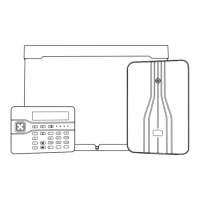
Step-by-step instructions for physically installing the panel, connecting power, and battery.

Routine Testing

Outlines daily, weekly, quarterly, and yearly testing procedures for system maintenance.

Faults

Specific Fault Indication

Explains specific fault LEDs (Power, Zone, Alarm, Earth, System) and their corresponding actions.

Related product manuals