S225-12-1
21
!
SAFETY
FOR LIFE
4. UsingaPhillipsheadscrewdriver,loosenandremove
the TCB terminal board leads from the 14 position
terminal board located on the top right of the QD3
tap-changer. (See Figure 40.)
TABLE 3
Lead Color and Termination Points
Lead Color TCB Connection
Blue/White 1
Green/White 5
Blue 9
Green 10
Orange 11
Red/Black 13
White G
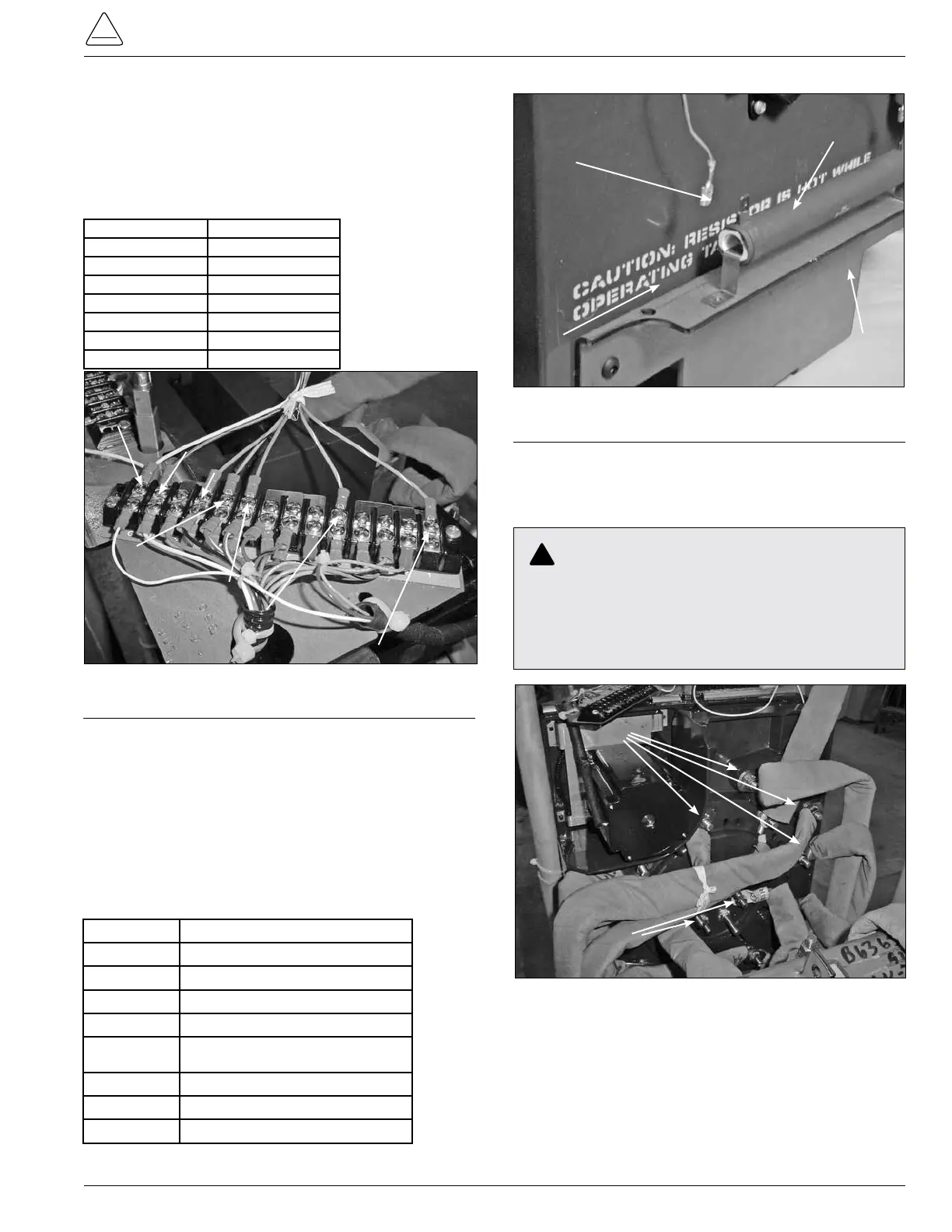
5. Use a Phillips head screwdriver and needle nose
pliers to disconnect the white E control winding leads
and P leads, if available, from the seven position
terminal board located on the left top of the tap-
changer. (See Figure 41.)
Control Winding E Lead and P Lead, if Available,
Connections.
TABLE 4
Lead Marker and Terminal Board ID
Lead Marker Terminal Board ID
E Could be on either E1, E2, or E3
E1 E1
E2 E2
E3 E3
P If available, could be on either P1, P2,
or P3
P1 P1
P2 P2
P3 P3
Figure 40.
TCB lead color and termination points.
White Position G
Red/Black Position 13
Green Position 10
Orange Position 11
Blue Position 9
Green/White Position 5
Blue/White Position 1
6. Use a deep well 9/16 inch socket with a ratchet
or a 9/16 inch wrench to loosen and remove all
lead connections from the back of the tap-changer
contact board. (See Figure 42.)
E3
E1
G
E2
Figure 41.
E & P lead connections.
CAUTION:
Do not remove lead ties from lead bundles holding
the tap leads in a certain position. Try to keep from
moving the lead bundles from normal position. Doing
so can result possibly in de-electric failures.
Figure 42.
Tap leads and reactor connections.
Tap Lead Connections
Reactor P1 & P2 Connections