QD3 Quik-Drive Voltage Regulator Tap-Changer Manual
30
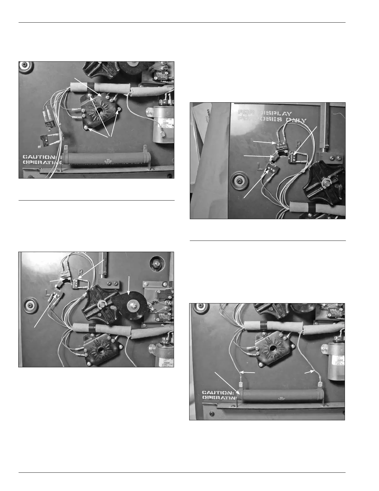
8. Fasten the tap position switch assembly to the front of
the drive panel assembly with three pan head Phillip
screws. (See Figure 75.)
9. Position the position actuator arm between the
center position and L by rotating the pinion counter
clockwise. (See Figure 76.) This will allow for mounting
the micro switches without interference with the micro
switch arms.
Figure 75.
Position switch assembly.
Screws
Position Switch
Assembly
Figure 76.
Switch actuator position.
Actuator
L Switch
Pinion
R Switch
10. Place and fasten the reversing logic and neutral logic
micro switches on the upper left of the drive assembly
panel. The micro switch with a blue white striped
wire and blue black striped wire is located on the R
position. The micro switch with a red white striped wire
and red black striped wire is located on the L position.
The micro switch with an orange wire and a white wire
is located on the center position between the R and L
position. (See Figure 77.)
11. Rotate the pinion back clockwise until the arm in Figure
77 is in the center and the neutral switch is depressed.
12. Connect the blue wires with red stripes to the 40-ohm
resistor by pushing the female connector onto the
resistor terminals. (See Figure 78.)
Figure 77.
Logic switch positioning.
Actuator Arm
L Switch
R Switch
Neutral
Figure 78.
Resistor connections.
Blue/Red Leads
Resistor