S225-12-1
29
!
SAFETY
FOR LIFE
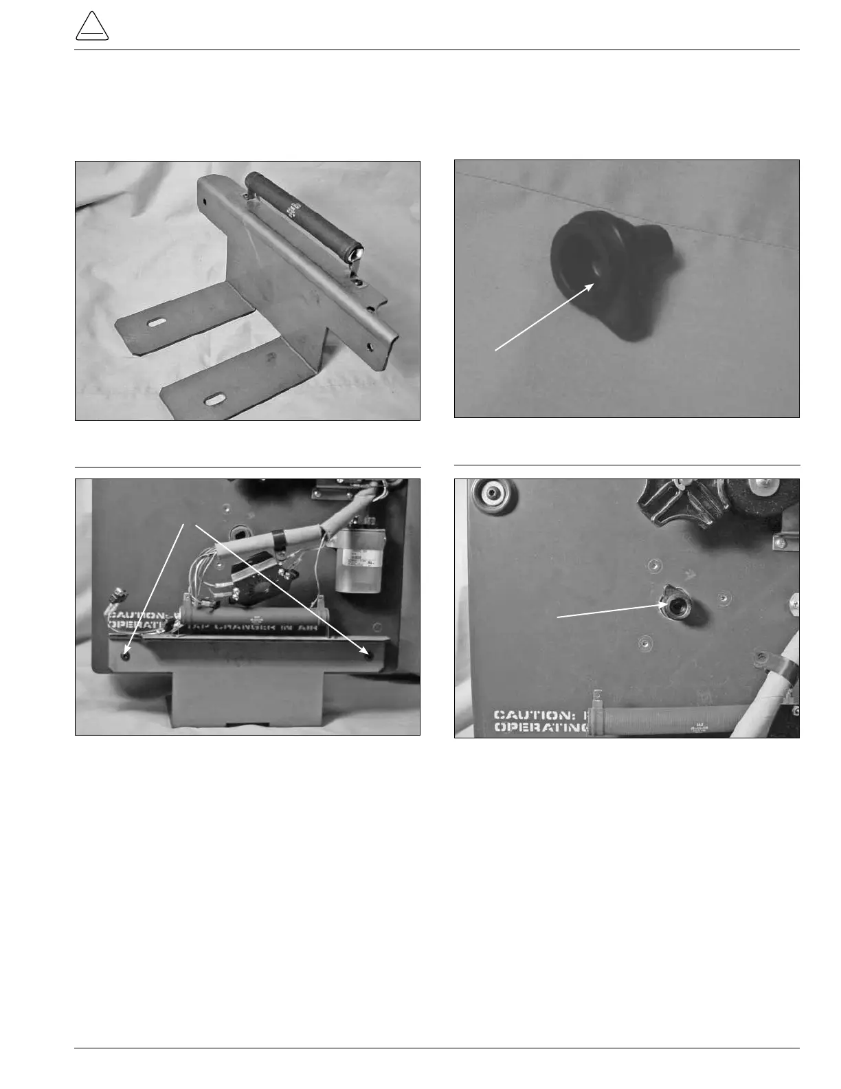
6. Place the mounting bracket (see Figure 71) to the
base of the tap-changer assembly and fasten with
two pan head hex screw and tighten with a 5/32 Allen
Wrench. (See Figure 72.)
Figure 71.
Tap-changer mounting bracket.
Figure 72.
Bracket fastening.
Fastening Screws
7. Place the neutral position pointer lob (see Figure 73)
into the main moveable contact hub located in the
lower front center of the drive assembly panel. (See
Figure 74.)
Figure 73.
Position indicator lob.
Figure 74.
Lob placement.
Lob
Lob