QD3 Quik-Drive Voltage Regulator Tap-Changer Manual
28
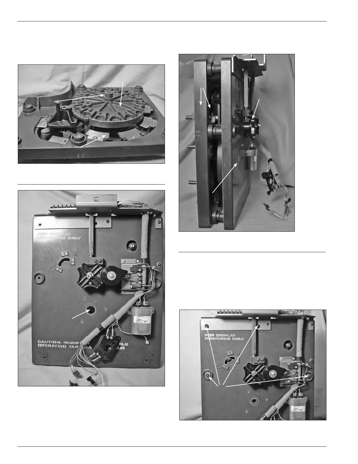
3. Align the center hub of the main moveable contact
assembly with the center hole in the tap-changer drive
assembly. (See Figures 67 and 68.)
Figure 67.
Contact assembly and main moveable contacts.
Hub
Figure 68.
Drive assembly panel.
Center Hole
Main Moveable
Contact Assembly
Stationary Contact Assembly
4. Press both of the tap-changer assembly sections
together and stand up-right. (See Figure 69.)
5.
Insert four pan head Allen screws into the tap-
changer assemblies. Two screws will mount the
two tap-changer assemblies and the terminal block
bracket at the top of the tap-changer. The other two
screws are inserted in the mounting holes along both
side centers of the tap-changer. (See Figure 70.)
Figure 69.
View of panel assembly.
Contact Panel
Drive Panel Assembly
Drive Assembly Panel
Figure 70.
Panel assembly fastening.
Screws