S225-12-1
33
!
SAFETY
FOR LIFE
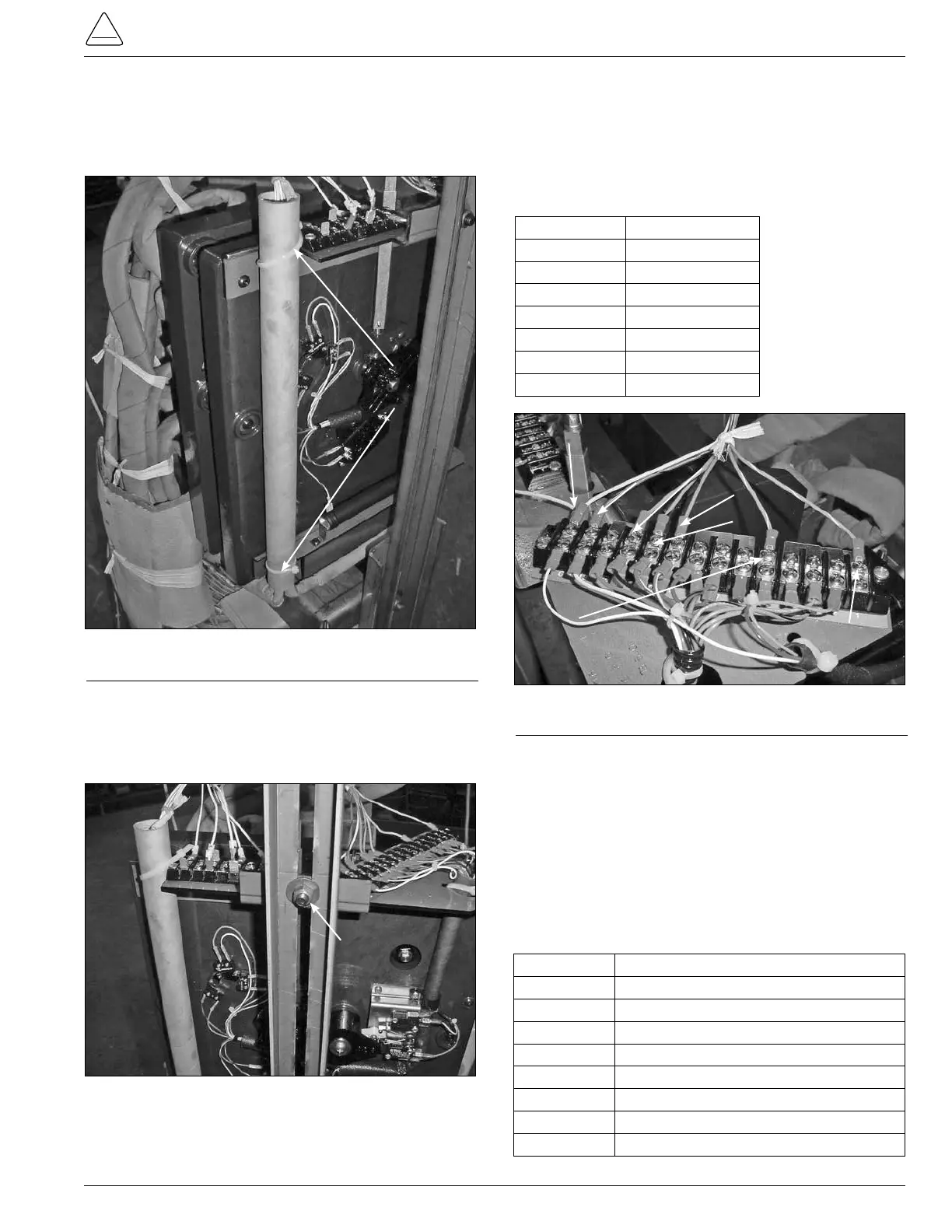
Figure 82.
Tap-changer and side channel fastener.
Cable Tie
Figure 81.
Control cable fastening.
3. Use a 9/16 inch socket and ratchet to loosen and
remove the nut and carriage bolt fastening the tap-
changer bracket to the regulator side channel. (See
Figure 82.)
Carriage Bolt Nut
4. Use a Phillips head screwdriver to loosen and
remove the TCB terminal board leads from the 14
position terminal board located on the top right of the
QD3 tap-changer. (See Figure 83.)
TABLE 7
Lead Color and Termination Points
Lead Color TCB Connection
Blue/White 1
Green/White 5
Blue 9
Green 10
Orange 11
Red/Black 13
White G
Figure 83.
TCB lead color and termination points.
White Position G
Red/Black
Position 13
Orange Position 11
Green Position 10
Blue Position 9
Green/White
Position 5
Blue/White
Position 1
5. Use a Phillips head screwdriver and needle nose
pliers to disconnect the white E control winding
leads, and P leads if available, from the seven
position terminal board located on the left top of the
tap-changer. See Figure 84.
Control winding E lead and (P lead if available)
Connections. The E lead will have E lead ID markers
and the P leads if available will have P lead markers.
TABLE 8
Lead Marker and Terminal Board ID
Lead Marker Terminal Board ID
E Could be on either E1, E2, or E3
E1 E1
E2 E2
E3 E3
P If available could be on either P1, P2, or P3
P1 P1
P2 P2
P3 P3
2. Use a pair of diagonal side cutters to cut and
remove the cable-ties from the control winding
hard insulation tube and tap-changer top bracket
assembly. (See Figure 81.)