S225-12-1
39
!
SAFETY
FOR LIFE
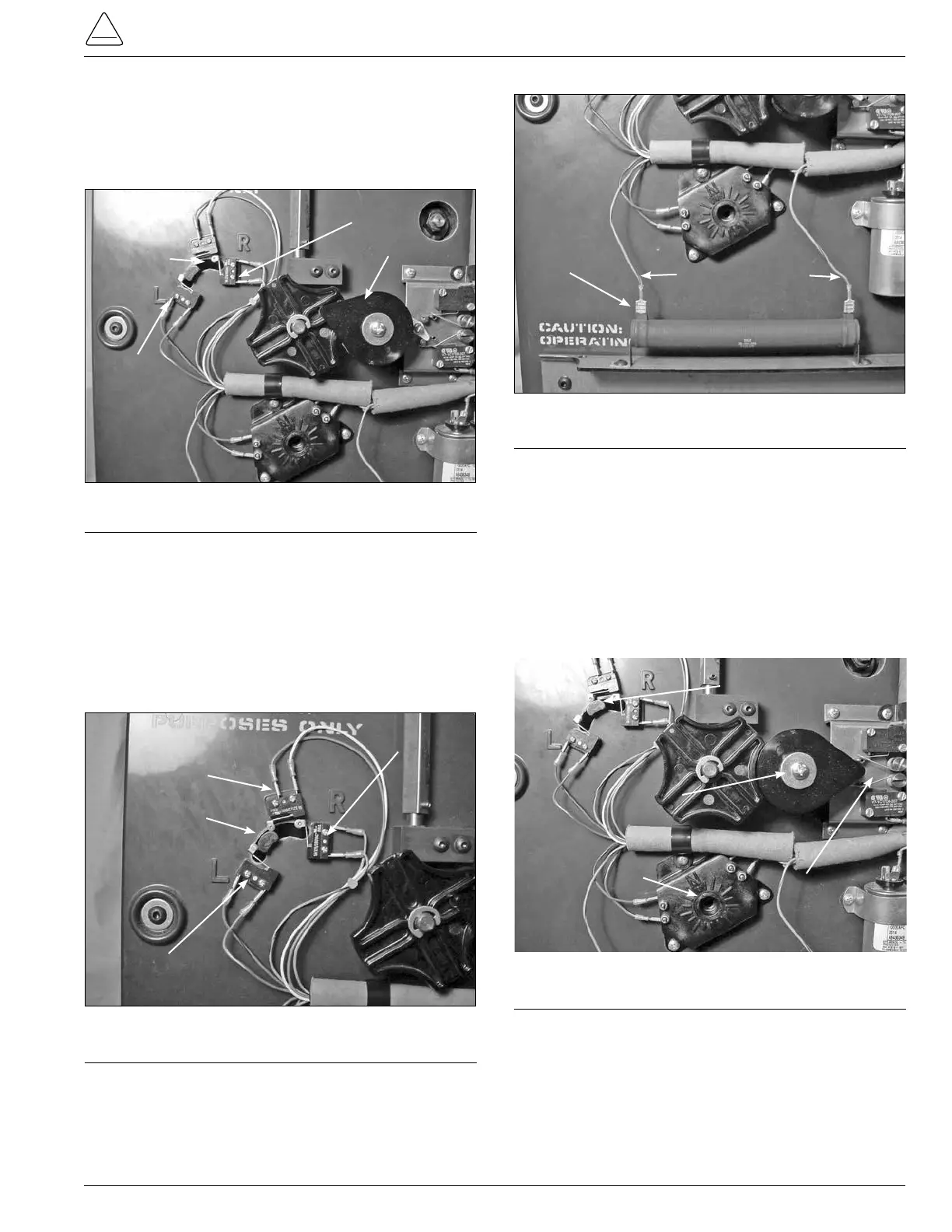
9. Position the position actuator arm between the center
position and L by rotating the pinion counter clockwise.
(See Figure 107.) This will allow for mounting the micro
switches without interference with the micro switch
arms.
Figure 107.
Switch actuator position.
Actuator
L Switch
R Switch
Pinion
10. Place and fasten the reversing logic and neutral logic
micro switches on the upper left of the drive assembly
panel. The micro switch with a blue white striped wire
and blue black striped is located on the R position.
The micro switch with a red white striped wire and red
black striped wire is located on the L position. The micro
switch with an orange wire and a white wire is located on
the center position between the R and L position. (See
Figure 108.)
Figure 108.
Logic switch positioning.
Neutral
Actuator Arm
L Switch
R Switch
11. Rotate the pinion back clockwise until the arm in Figure
108 is in the center and the neutral switch is depressed.
12. Connect the blue wires with red strips to the 40 ohm
resistor by pushing the female connector on to the resis-
tor terminals. (See Figure 109.)
Blue/Red Leads
Resistor
Figure 109.
Resistor connections.
13. Check and set the tapchanger for neutral position. The
tapchanger can be set for any tap position by rotating
the pinion cam in either the clockwise or counter clock-
wise direction. For neutral position the reversing logic
switch actuator must be in the center with the neutral
switch arm depressed. The tap position lob must have
the pointer pointing at N. The pinion cam point is point-
ing at the three o’clock position over the holding switch
lever arm. The holding switch is open. (See Figure 110.)
Figure 110.
Neutral positioning.
Pinion Cam Pointing
at three o'clock
Reversing
Logic Switch
Tap Position Lob
Pointing at N
Holding Switch
Open
Re-Assembly of Tap-Changer to Voltage
Regulator Assembly
1. Once the tapchanger has been reassembled, reverse
the process in the procedure titled “Tapchanger Remov-
al from Voltage Regulator” at the beginning of the instal-
lation instructions.