QD3 Quik-Drive Voltage Regulator Tap-Changer Manual
38
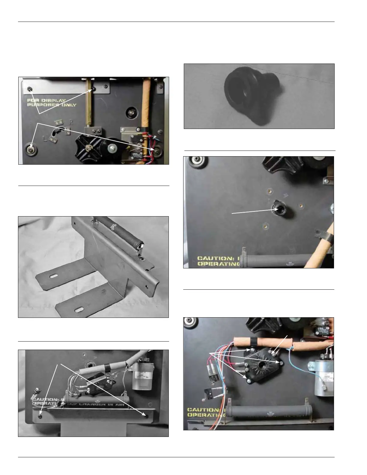
Figure 102.
Tap-changer mounting bracket.
6. Place the mounting bracket (see Figure 102) to the base
of the tapchanger assembly and fasten with two pan
head hex screw and tighten with a 5/32 Allen Wrench.
(See Figure 103.)
Fastening Screws
Figure 103.
Bracket fastening.
7. Place the neutral position pointer lob, see (Figure 104),
into the main moveable contact hub located in the lower
front center of the drive assembly panel. (See Figure
105.)
Figure 104.
Position indicator lob.
Figure 105.
Lob placement.
Lob
8. Fasten the tap position switch assembly to the front of
the drive panel assembly with three pan head Phillip
screws. (See Figure 106.)
Figure 106.
Position switch assembly.
Screws
Position Switch
Assembly
5. Insert four pan head Allen screws into the tapchanger
assemblies. Two screws will mount the two tapchanger
assemblies and the terminal block bracket at the top of
the tapchanger. The other two screws are inserted in
the mounting holes along both side centers of the tap
changer. (See Figure 101.)
Figure 101.
Panel assembly fastening.
Screws