S225-12-1
37
!
SAFETY
FOR LIFE
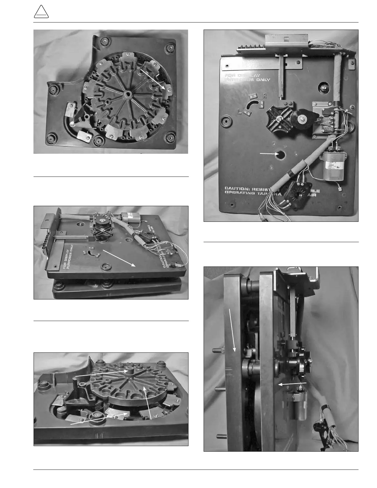
Figure 96.
Stationary contact panel assembly.
Figure 97.
Tap-changer sections.
Drive Panel Assembly
Stationary
Contact
Panel
Assemble
3. Align the center hub of the main moveable contact
assembly with the center hole in the tapchanger drive
assembly. (See Figures 98 and 99.)
Figure 98.
Contact assembly and main moveable contacts.
Hub
Stationary
Contact
Assembly
Man Moivable
Contact Assembly
Figure 99.
Drive assembly panel.
Center Hole
4. Press both of the tapchanger assembly sections
together and stand upright. (See Figure 100.)
Figure 100.
View of panel assembly.
Contact Panel
Drive Panel
Assembly
2. Place and align the tapchanger drive assembly section
on top of the contact panel assembly. (See Figure 97.)