S225-12-1
41
!
SAFETY
FOR LIFE
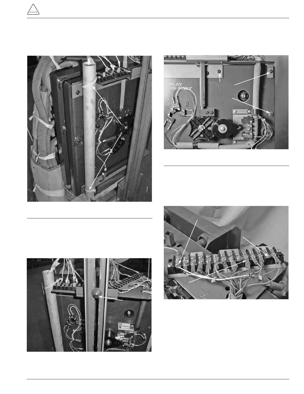
2. Use a pair of diagonal side cutters and cut and remove
the cable ties from the control winding hard insulation
tube and tapchanger top bracket assembly. (See
Figure 113.)
Cable Tie
Figure 113.
Control cable fastening.
3. Use a 9/16 inch socket and ratchet to loosen and
remove the nut and carriage bolt fastening the tap
changer bracket to the regulator side channel. (See
Figure 114.)
Figure 114.
Tap-changer and side channel fastener.
Carriage Bolt
Nut
4. Using a 1/8 inch Allen wrench, remove the three button
Allen head screws fastening the motor bracket to the
tapchanger assembly. (See Figure 115.)
Figure 115.
Motor bracket fasteners.
1/8 inch
Allen Head
Screws
5. Using a Phillips screwdriver, loosen and remove the
blue motor lead terminal from the tapchanger larger
terminal board terminal position 2, red lead from
terminal position 6 and the white ground lead from
terminal position G. (See Figure 116.)
Blue Lead Terminal 2
White Ground Lead Terminal G
Red Lead Terminal 6
Figure 116.
Motor wiring to terminal board.