S225-12-1
45
!
SAFETY
FOR LIFE
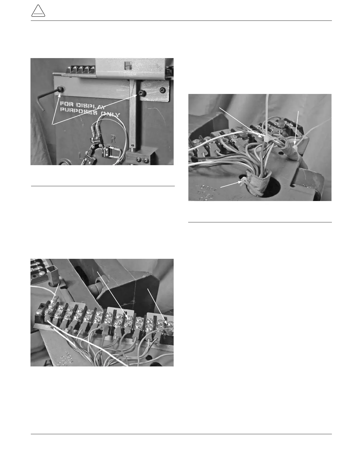
23. Place the 5/32 inch button Allen head screws in the
top bracket and front plate, tightening with a 5/32 Allen
wrench. (See Figure 129.)
24. The inside 1/8 inch motor mounting button head screw
may be easier to start after tightening the 5/32 inch but-
ton Allen head screws.
25. Crimp a ring tongue terminal item #1 to each of the mo-
tor wires after cutting and stripping to t.
26. Connect the blue motor wire to post 2 of the large termi-
nal board, connect the red wire to past 6, and the white
wire to the ground post G. (See Figure 130.)
5/32 inch Button Allen Head Screws
Figure 129.
Terminal board bracket fastening.
White "G" Post
Red Post 6
Blue Post 2
27. Use two cable ties item #2, to fasten the motor leads to
the main wiring harness.
28. Place the insulation paper tubing and motor wires in the
bracket slots at the end of the bracket above the motor
and cable tie with one item #3. (See Figure 131.)
29. Bundle with plastic cable ties the main wiring harness
insulator tube to the bracket with one cable tie, item #3.
(See Figure 131.)
30. Place the carriage bolt into the square hole of the tap
changer top bracket. Place the 9/16 nut onto the bolt
through the side channel and tighten with the socket
and ratchet. (See Figure 114.)
31. Place the control winding hard tubing insulation against
the tapchanger top bracket and bundle with plastic
cable ties with item #3. (See Figure 113.)
Figure 130.
Terminal board wiring.
Motor Harness Tie
Motor
Insulation Tie
Main Harness Tie
Figure 131.
Wiring insulation fastening.