QD3 Quik-Drive Voltage Regulator Tap-Changer Manual
44
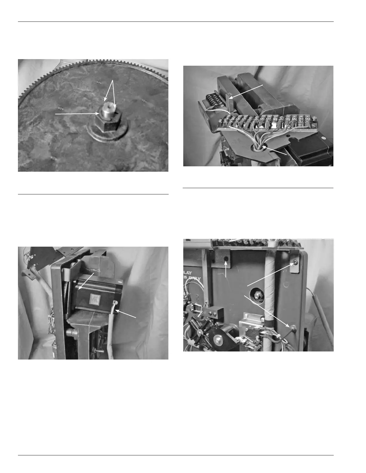
18. Using a pair of needle nose pliers, press the "E" clip over
the motor shaft grove. The center "E" Clip point must be
on the at surface of the motor shaft. (See Figure 125.)
19. With the motor leads to the outside, place the motor
gear between the tapchanger sections. The motor
gear must match up with the pinion drive gear. (See
Figure126.)
20. Place one drop of locktite on each motor button Allen
head screw thread (1/8).
EClip
Figure 125.
E-Clip placement.
Shift Flat Surfaces
Motor and Gear
Motor Leads
Figure 126.
Motor placement.
21. Position the top bracket so that the position indicator
drive tube and main wiring harness is through the bracket
holes. Align the bracket and motor mounting holes. (See
Figure 127.)
22. Place the 1/8 inch button Allen head screws into the right
side and right top of the plate. The bottom right screw
also requires a at washer. (See Figure 128.) Use a 1/8
inch Allen wrench and tighten the connection between
the motor bracket and the front plate.
Position Indicator Drive Tube
Main Wiring Harness
Figure 127.
Terminal board bracket alignment.
Motor
Mounting
Screws
Figure 128.
Motor bracket fasteners.