S225-12-1
43
!
SAFETY
FOR LIFE
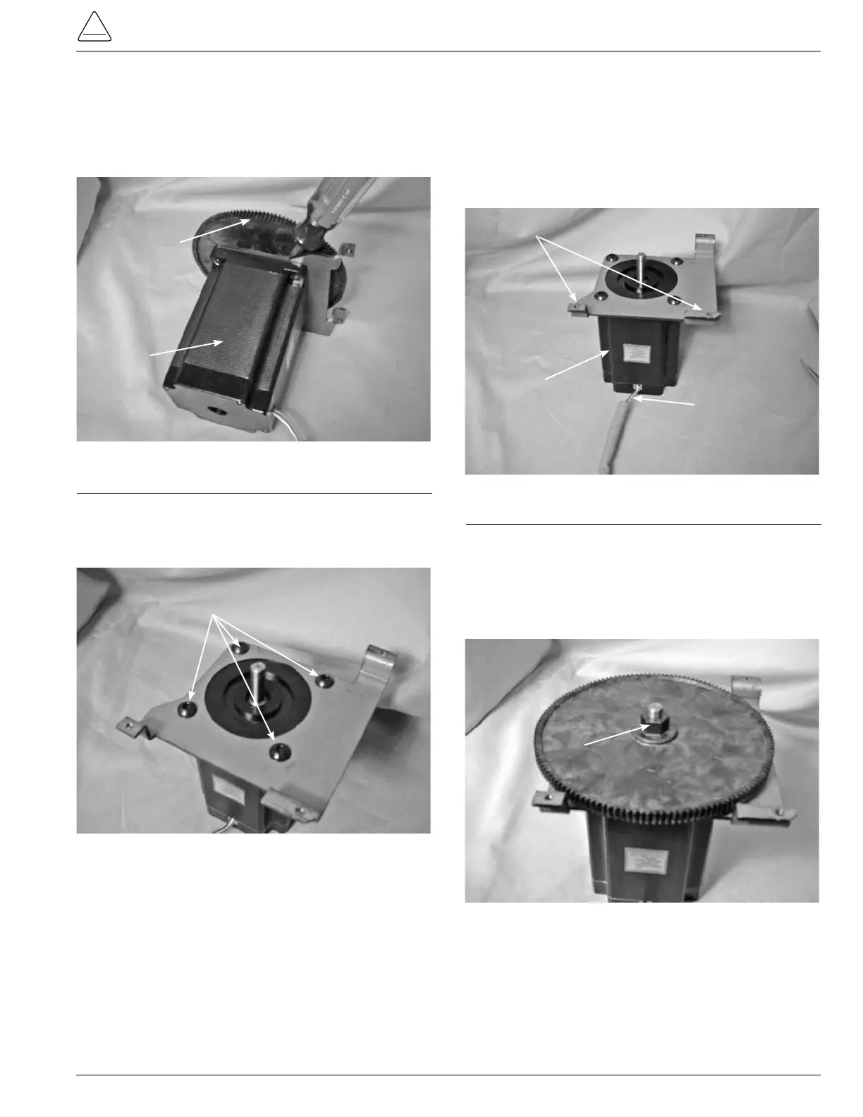
12. To remove the gear from the motor, use a standard
screw driver to pry the gear off of the motor shaft. Place
the screwdriver between the motor and the gear. Pry
the gear forward until the gear clears the shaft. (See Fig-
ure121.)
13. Using a 3/16 inch Allen wrench, loosen and remove the
Allen button head screws fastening the bracket to the
motor. (See Figure 122.)
Motor Gear
Motor
Figure 121.
Motor and gear.
3/16 inch Allen Head Screws
New Motor Assembly
14. Place the red, blue, and white motor leads through item
#4 creep insulation.
15. Position the motor onto the motor mount bracket so
that the motor leads are on the side where there are two
mounting ears. (See Figure 123.)
16. Fasten the motor mount bracket onto the motor using
four button Allen head 3/16 inch screws and tighten with
a 3/16 inch Allen wrench.
17. Place the motor gear onto the motor shaft with the hex
nut to the outside. (See Figure 124.)
Motor
Motor Bracket Mounting Ears
Motor Leads
Figure 123.
Motor and bracket alignment.
Figure 122.
Motor bracket.
Figure 124.
Motor gear placement.
Gear Hex Nut