QD3 Quik-Drive Voltage Regulator Tap-Changer Manual
58
Figure 170.
Tap-changer mounting bracket.
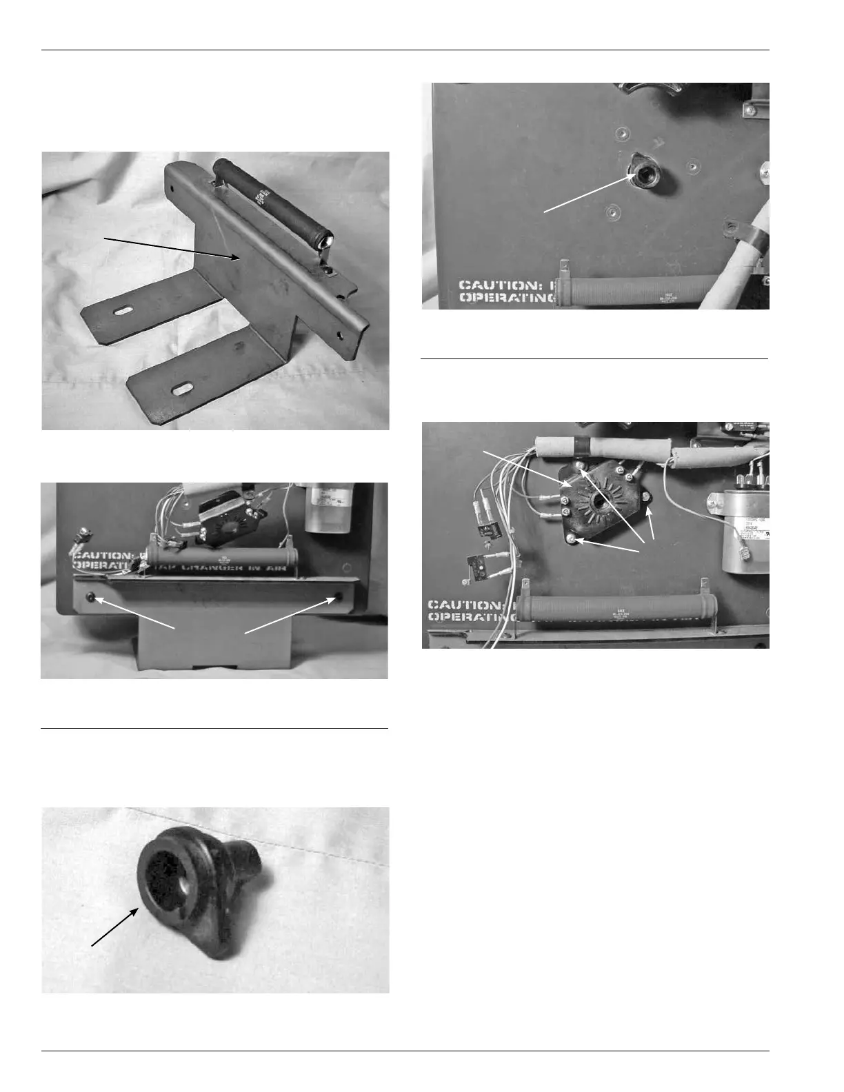
6. Place the mounting bracket, (see Figure 170), to the base
of the tapchanger assembly and fasten with two pan
head hex screw and tighten with a 5/32 Allen Wrench.
(See Figure 171.)
Drive Panel
Figure 171.
Bracket fastening.
Fastening
Screws
7. Place the neutral position pointer lobe, (see Figure 172),
into the main moveable contact hub located in the lower
front center of the drive assembly panel. (See Figure 173.
)
Figure 172.
Position lob indicator.
Lob
Figure 173.
Lob placement.
Lob
8. Fasten the tap position switch assembly to the front of
the drive panel assembly with three pan head Phillip
screws. (See Figure 174.)
Figure 174.
Lob placement.
Screws
Position
Switch