S225-12-1
57
!
SAFETY
FOR LIFE
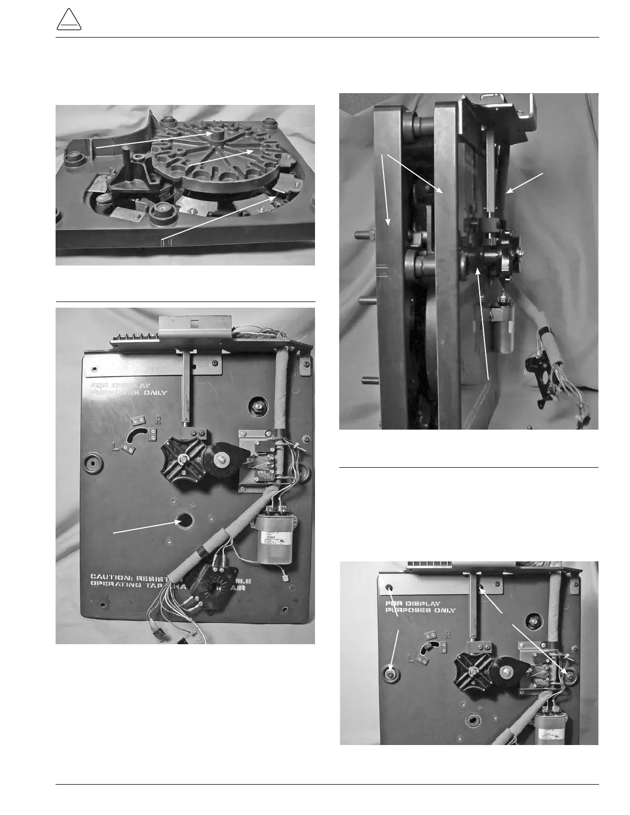
Figure 168.
Tap-changer sections.
3. Align the center hub of the main moveable contact
assembly with the center hole in the tapchanger drive
assembly. (See Figures 166 & 167.)
Figure 166.
Contact assembly and main moveable contacts.
Figure 167.
Drive assembly panel.
Stationary Contact
Main Moveable
Contact
Hub
Center Hole
4. Press both of the tapchanger assembly sections togeth-
er and stand upright. (See Figure 168.)
Contact Panel
Drive Panel
Drive Assembly
Panel
5. Insert four pan head Allen screws into the tapchanger
assemblies. Two screws will mount the two tapchanger
assemblies and the terminal block bracket at the top of
the tapchanger. The other two screws are inserted in
the mounting holes along both side centers of the tap
changer. (See Figure 169.)
Figure 169.
Panel assembly fastening.
Screws
Screws