S225-12-1
61
!
SAFETY
FOR LIFE
Tap-changer Removal from
Voltage Regulator
1. Remove the internal position indicator shaft from the
tapchanger indicator drive tube. (See Figure 181.)
Figure 181.
Internal flex shaft.
Internal Flex
Tapchanger
Internal Drive Tube
2. Use a pair of diagonal side cutters cut and remove the
cableties from the control winding hard insulation tube
and tapchanger top bracket assembly. (See Figure
182.)
Figure 182.
Control cable fastening.
Cable Tie
3. Use a 9/16 inch socket and ratchet to loosen and
remove the nut and carriage bolt fastening the tap
changer bracket to the regulator side channel. (See
Figure 183.)
Figure 183.
Tap-changer and side channel fastener.
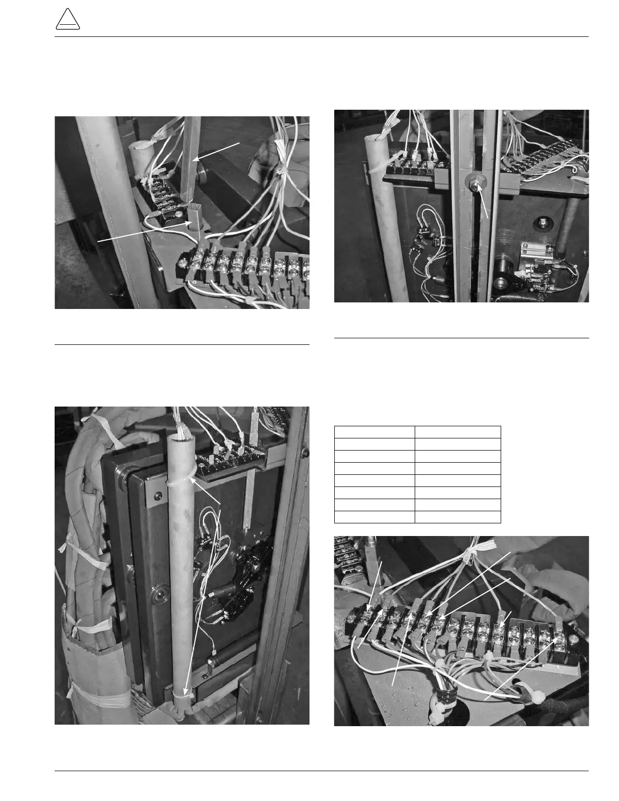
4. Using a Phillips head screwdriver, loosen and remove
the TCB terminal board leads from the 14 position
terminal board located on the top right of the QD3 tap
changer. (See Figure 184.)
TABLE 21
Lead Color and Termination Points
Lead Color TCB Connection
Blue/White 1
Green/White 5
Blue 9
Green 10
Orange 11
Red/Black 13
White G
Figure 184.
TCB lead color and termination points.
White Position G
Red/Black
Position 13
Orange
Position 11
Green
Position 10
Blue
Position 9
Green/White
Position 9
Blue/White
Position 9
Carriage Bolt Nut