QD3 Quik-Drive Voltage Regulator Tap-Changer Manual
62
5. Use a Phillips head screwdriver and needle noise pliers
to disconnect the white E control winding leads and P
leads if available from the seven position terminal board
located on the left top of the tapchanger. (See Figure
185.)
Control Winding E Lead and (P Lead if Available) Connections
The E lead will have E lead ID markers and the P
leads, if available, will have P lead markers.
TABLE 22
Lead Marker and Terminal Board ID
Lead Marker Terminal Board ID
E Could be on either E1, E2, or E3
E1 E1
E2 E2
E3 E3
P If available, could be on either P1,
P2, or P3
P1 P1
P2 P2
P3 P3
6. Use a deep well 9/16 inch socket with ratchet or
a 9/16 inch wrench to loosen and remove all lead
connections from the back of the tapchanger contact
board. (See Figure 186.)
Figure 185.
E & P lead connections.
E3
E2
E1
G
CAUTION:
Do not remove lead ties from lead bundles holding
the tap leads in a certain position. Try to keep from
moving the lead bundles from normal position. Doing
so can result possibly in de-electric failures.
Figure 186.
Tap leads and reactor connections.
Tap Lead
Connections
Reactor P1 & P2
Connections
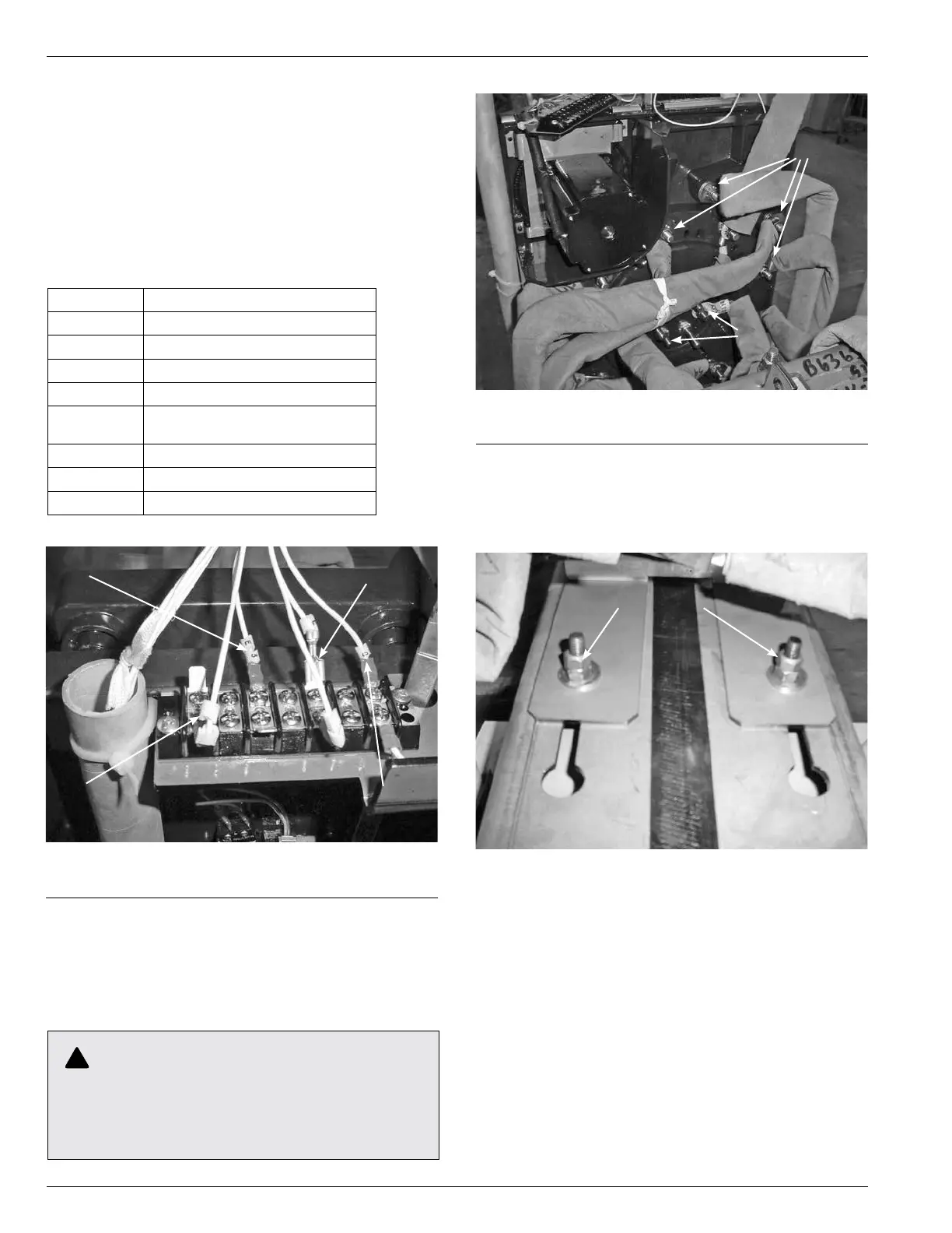
7. Remove the mounting bolts fastening the tapchanger
mounting bracket to the top core clamp. (See Figure
187.) Remove the tapchanger from the regulator and
place on a work surface.
Figure 187.
Tap-changer to core clamp fastening hardware.
Mounting
Hardware