S225-12-1
63
!
SAFETY
FOR LIFE
QD3/T350 Tap-Changer Assembly
Separation
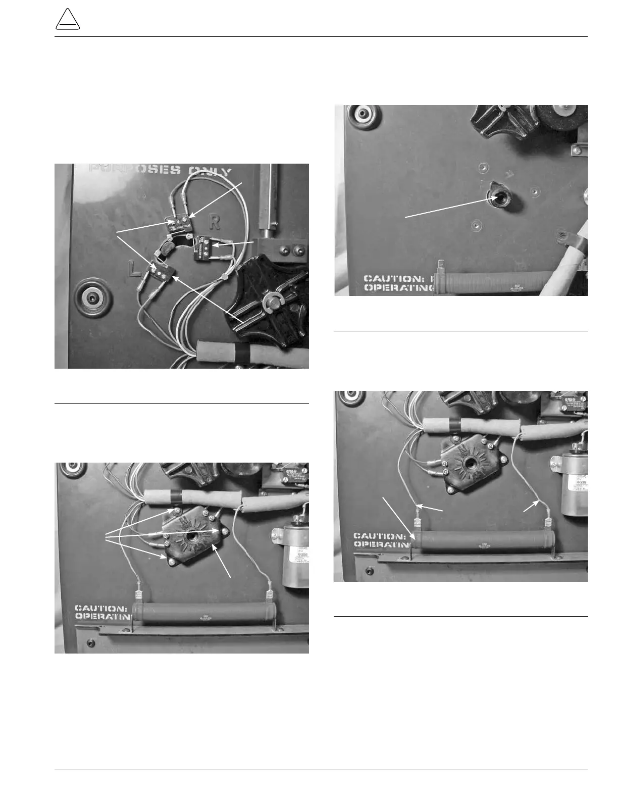
8. After removing the tapchanger from the regulator
assembly, use a Phillips head one point screwdriver
too loosen and remove the six screws mounting the
Reversing Lower, Raise and Neutral switch located in
the upper left corner of the tapchanger assembly. (See
Figure 188.)
9. Using a Phillips head screwdriver, loosen and remove
the three mounting screws fastening the position
indicator micro switch hub to the front of the tapchanger
assembly. (See Figure 189.)
Figure 188.
Lower, raise and neutral logic switches.
Screws
Neutral
Raise
Lower
Figure 189.
Position indicator hub.
Screws
Position Indicator Hub
10. Remove the tapping indicator position lob pointer from
the tapchanger. The lob may have to be pried a little to
be removed. (See Figure 190.)
11. Disconnect and remove the blue and red strip leads from
the 40Ohm resistor. These connections are pushon
connections. (See Figure 191.)
12. Lay the tapchanger assembly flat on a work surface
with the tap contact studs down on the surface.
Figure 190.
Indicator position lob.
Indicator Position Lob
Figure 191.
40 Ohm resistor connections.
40 Ohm Resistor
Blue/Red Leads