QD3 Quik-Drive Voltage Regulator Tap-Changer Manual
70
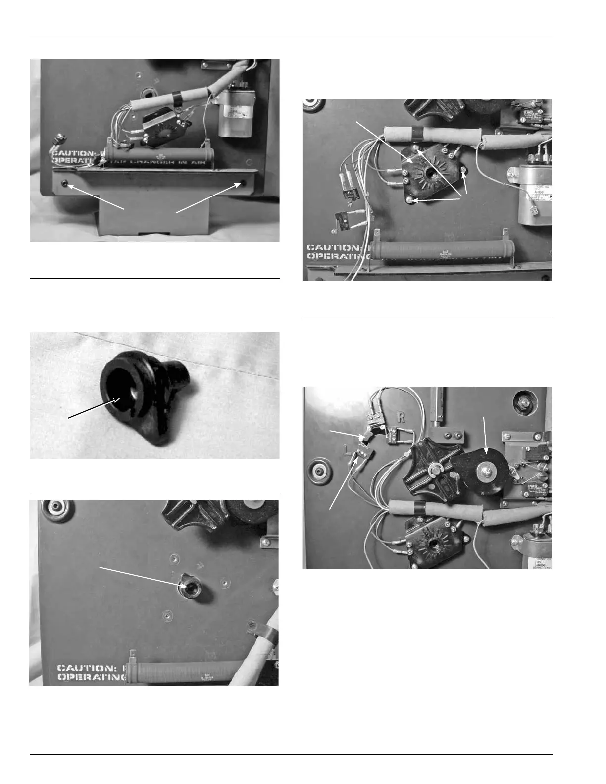
Figure 216.
Bracket fastening.
Fastening
Screws
7. Place the neutral position pointer lob, (see Figure 217),
into the main moveable contact hub located in the lower
front center of the drive assembly panel. (See Figure
218. )
Figure 217.
Position indicator lob.
Figure 218.
Lob placement.
Lob
Lob
Figure 219.
Position switch assembly.
Position Switch Assembly
Screws
8. Fasten the tapposition switch assembly to the front
of the drive panel assembly with three pan head Phillip
screws. (See Figure 219.)
9. Position the position actuator arm between the center
position and L by rotating the pinion counter clockwise.
(See Figure 220.) This will allow for mounting the micro
switches without interference with the micro switch
arms.
Figure 220.
Lob placement.
Actuator
L Switch
Pinion