S225-12-1
69
!
SAFETY
FOR LIFE
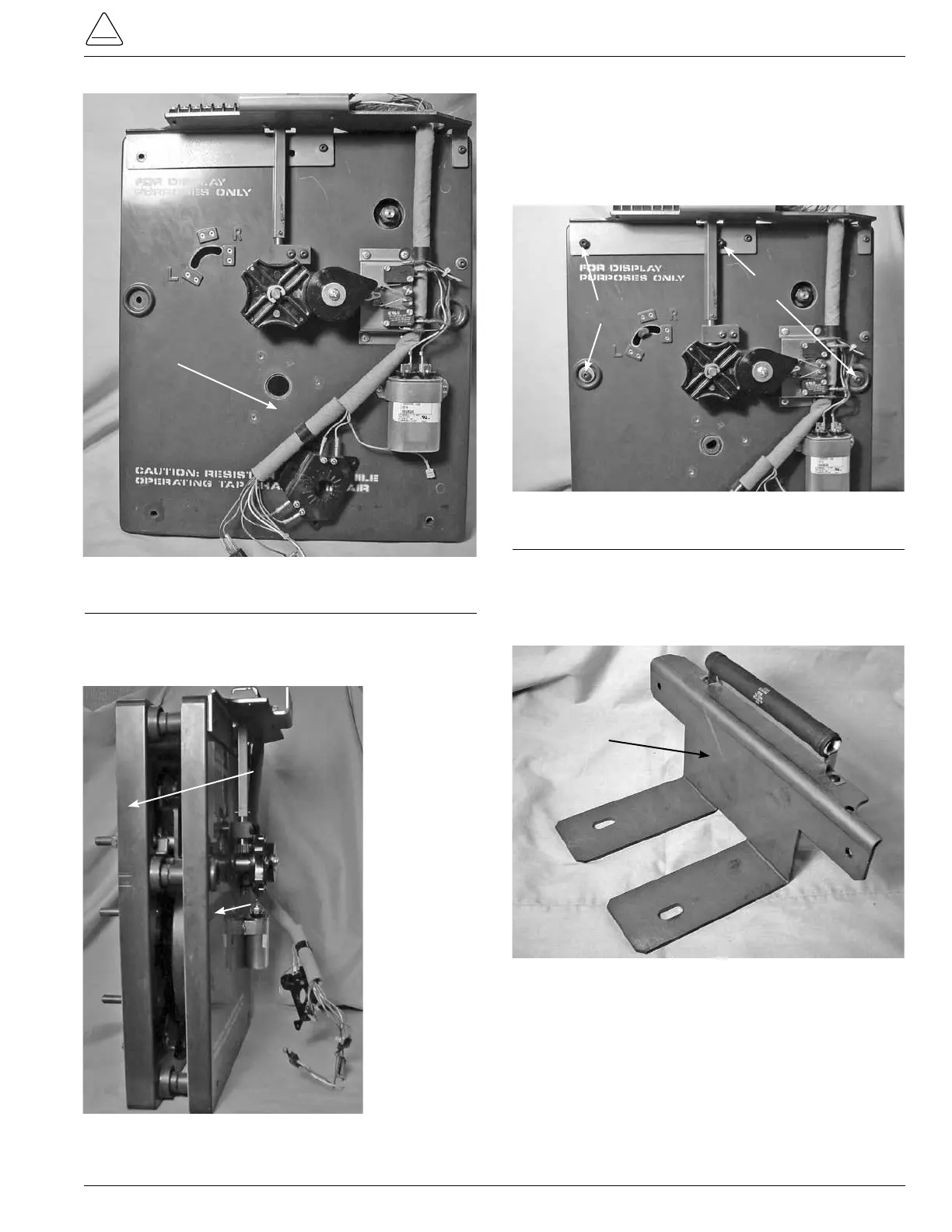
Figure 212.
Drive assembly panel.
Center Hole
4. Press both of the tapchanger assembly sections
together and standupright. (See Figure 213.)
Figure 213.
View of panel assembly.
Contact
Panel
Drive Panel
Assembly
5. Insert four pan head Allen screws into the tapchanger
assemblies. Two screws will mount the two tapchanger
assemblies and the terminal block bracket at the top of
the tapchanger. The other two screws are inserted in
the mounting holes along both side centers of the tap
changer. (See Figure 214.)
6. Place the mounting bracket, (see Figure 215), to the base
of the tapchanger assembly and fasten with two pan
head hex screw and tighten with a 5/32 Allen Wrench.
(See Figure 216.)
Figure 214.
Panel assembly fastening.
Figure 215.
Tap-changer mounting bracket.
Screws
Screws
Contact
Panel