■ The following recommendations must be observed
during installation:
■ Avoid the frame receiving the lateral tension and
pressure, causing deformations or cracking of the glass.
■ Before installing modules on a roof, always ensure the
roof construction is suitable. In addition, any roof
penetration required to mount the module must be
properly sealed to prevent leaks.
■ Observe and take into account the linear thermal
expansion of the module frames (the recommended
minimum distance between two modules is 1 cm).
■ When installing the module on the column, choose the
column and module installation structure that can
withstand the expected local wind and snow load.
■ Ensure that the modules are not subjected to wind
pressure or snow load in excess of the maximum
permissible values and are not subjected to excessive
forces as a result of thermal expansion of the structures.
Under no circumstances should modules overlap or
protrude beyond the outline of the roof. For more detailed
information, see the description of installation methods
below.
Installation methods
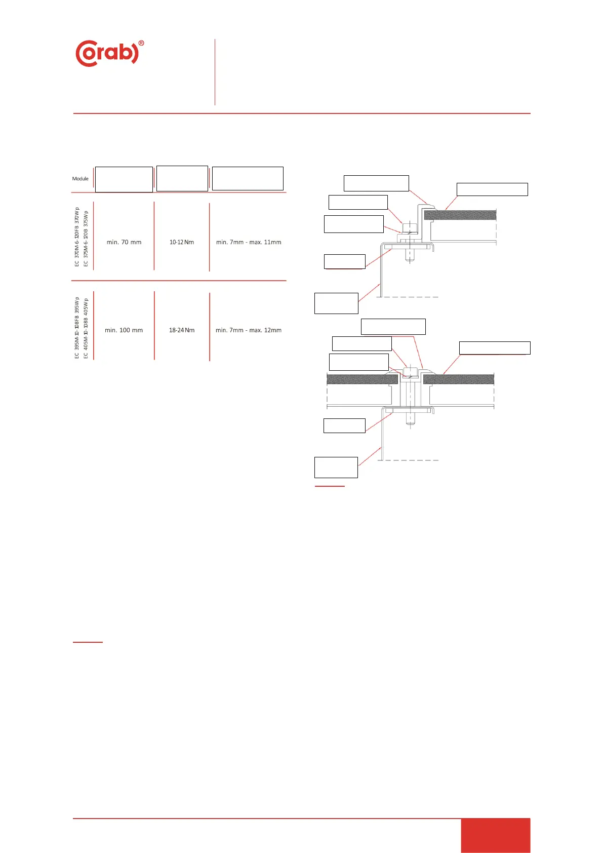
Mounting with clamps
When choosing this type of clamp-mounting method, use
at least four clamps on each module, two clamps should be
attached on each long sides of the module (for portrait
orientation) or each short sides of the module (for
landscape orientation). The minimum recommended
length for each fixture shall be 50 mm. Depending on local
wind and snow loads, additional clamps may be required
to ensure that modules can bear the load.
Modules clamps should not come into contact with the
front glass and must not deform the frame. Be sure to
avoid shadowing effects from the module clamps. The
mounting details are shown in the following figures.
Fastening guidelines
The standard/lower loading capacity applies to normal
environment: the modules are tested under a maximum
positive pressure of 2400 Pa, and negative pressure of
1600 Pa or 2400 Pa, the modules are designed to meet a
maximum positive pressure of 1600 Pa, and negative
pressure of 1067 Pa, this design load was then tested with
a safety factor of 1.5 times.
The high loading capacity applies to severe environment,
like storm, big snow, etc. The modules are tested under a
maximum positive pressure of 5400 Pa, and negative
pressure of 2400 Pa, the modules are designed to meet a
maximum positive pressure of 3600 Pa, and negative
pressure of 1600 Pa, this design load was then tested with
a safety factor of 1.5 times.
 Loading...