1. Placethe5/8”boltthroughtheshaftclampholeonthe
rearofhandle,andthe¾”boltthroughtheshaftclamp
onthefrontpartofthehandle.UsingtheT25bit,tighten
theshaftclampssothegriphandleissnugtotheshaft.
2. Placethelockoutleveronthepostasshowninpicture2,
withthespringpre‐loaded.
3. PlacetheTriggerdownonit’spostwiththespring
preloaded,asshowninpicture3.
4. RoutewirebacktoPowerHousingandplugwire
connectorbackintoController.
HARDWAREANDPARTSREQUIRED:
‐RIGHTSIDEOFRHGRIP“B”
‐(2)SHAFTCLAMPS
‐(2)10‐325/16NUT
‐(1)10‐32¾BOLT
‐(1)10‐325/8BOLT
‐(4)RIGHTHANDGRIPSCREW
‐TRIGGER
‐TRIGGERSPRING
TOOLS:
‐(2)ELECTRIC/SCREWGUN,T25ANDT18BITS
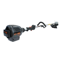
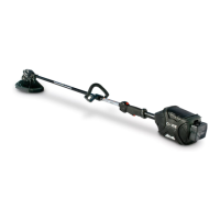
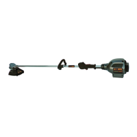
PowerHousing/GripHandleAssembly
3.
2.
1.
 Loading...