Figure 2.1: Typical installation.
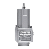
Features of the T166 Automatic
External Bypass Valve
The CORKEN T166 external bypass valve is designed
for use with truck pumps. It controls the pump
discharge pressure and bypasses excess liquid back
to the truck tank.
This bypass valve can also be used in stationary
applications utilizing sliding vane pumps.
Chapter 2—Installation of the T166
Automatic External Bypass Valve
Proper installation ensures optimum performance of the
pump and external bypass valve. Install the T166 external
bypass valve on the discharge side of the pump in either
a vertical or horizontal position. The discharge piping of
the bypass valve typically connects to the vapor section
of the truck tank using a back check valve. A typical truck
installation is shown in Figure 2.1. The recommended
pipe size for the discharge line is given in the table below.
For distances of 50 feet or more, the next larger pipe size
should be used.
Stationary applications with internal relief valves:
When the T166 external bypass valve is used for vapor
venting, the piping should be the same size used with the
B166 external bypass valve.
To ensure optimum performance of the external bypass
valve and the entire pumping system, follow the instructions
in this manual.
Pipe Size for the Discharge Line
Flow Rate
Pipe Size by Model Number
T166-1.25 T166-1.5
Up to 80 GPM 1-1/4" —
Up to 100 GPM — 1-1/2"
2.1 Operation of the T166
Automatic External Bypass Valve
Truck Applications:
The differential pressure setting of the B166 external bypass
valve is adjustable. The range of differential pressure
depends on the size of the spring installed in the bypass
valve. When the bypass valve ships from the CORKEN
factory, a tag identifying the spring size is attached to the
valve bonnet. The table below shows the part number
and differential pressure range for each spring. All of the
springs are interchangeable with each valve size.
Valve Model Spring Number
Differential Pressure
(PSIG)
T166
113 8 25–60
1193 50–150
1193
100–225
1313
1. Install liquid-filled pressure gauges equipped with a
needle valve or snubber in the following locations:
a. Pump discharge gauge port or Inlet side of the
bypass valve.
b. Supply tank and/or pump suction.
Bypass Valve
Pump
7