17
B 268 - XSE 602 C1 Eng.
22.11.10 AM REV. 02
We reserve the right to make changes witout notice
COSTER
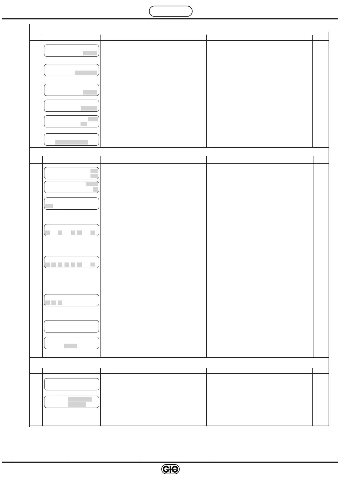
25. CONFIGURATION CONTROLLER
Ref. Display Description Notes Sect.
N a m e H t g P l a n t 2
- - - - - - - - - -
24.16
Entering name heating zone 2
15.
4
Use + and – to enter letters or numbers
Use
← and → to position cursor
H e a t i n g P u m p : A U T
D e l a y O f f : 3 0 m i n
24.15
Control plant pump: MAN; AUT.
Delay switching off pump
12.
12
Valve and pump LEDs of heating zone 2 blink
MAN: always On
AUT: On with events of current programme
C h o i c e K e y n u m b e r
- - - -
25.8
Choice keynumber for preventing modification data
by + and – keys.
– 1901 … 1999
15.
3
To eliminate keynumber press + and – together.
O p t i m u m S t a r t
B o o s t i n g 3 . 0 c
24.11
Increase in desired ambient temp. during optimu-
mstart period
13.
7
Valve and pump LEDs of heating zone 2 blink
C o o l i n g T i m e
C o n s t a n t : 4 8 . 0 0 h
24.12
Used when ambient detector B3 not installed to
calculate decrease in ambient temp.
13.
8
Valve and pump LEDs of heating zone 2 blink
O p t i m u m S t o p
D e c r e a s e T A 0 . 5 c
24.13
Reduction in desired ambient temp. at last event
end occupancy
13.
9
Valve and pump LEDs of heating zone 2 blink
O p t i m u m S t o p
M a x D u r a t : 1 . 0 0 h
24.14
Maximum duration period optimum stop
13.
10
Valve and pump LEDs of heating zone 2 blink
24. SETTING HEATING ZONE 2
Ref. Display Description Notes Sect.
S e n d A l a r m s : N O
P a s s W T e l e m a n : N O
25.1
Enabling alarms to send to telemanagement PC
Enabling telemanagement keynumber
10.
5
Only if connected in C-Bus
E n a b l e R e m o t e
N O
25.3
NO = remote control excluded
HEATING ZONE 1= remote control zone1;
HEATING ZONE2= remote control zone 2;
HEATING ZONES= remote control for both zones
12.
11
Only if connected in C-Bus
A d d r e s s : – – –
G r o u p : –
25.2
Telemanagement address of controller
Group to which controller assigned
10.
4
F u n c t i o n a l A l a r m s
– – – – 8
25.4
Disabling functional alarms
Factory setting : only 8 enabled (cannot be disa
-
bled)
16.
1
1 : Alarm difference temp. flow 1 B1
3 : Alarm difference temp. ambient 1 B3
5 : Alarm difference temp. flow 2 B5
6 : Alarm difference temp. ambient 2 B6
8 : Alarm internal real time clock
D e t e c t o r A l a r m s
1 2 3 4 5 6 8
25.5
Enabling alarms detector short or open circuits.
Factory setting : all enabled.
16.
2
1 : Flow 1 detector B1
2 : Outside detector B2
3 : Ambient 1 detector B3
4 : Anticondensing detector B4
5 : Flow 2 detector B5
6 : Ambient 2 detector B6
8 : C-Ring alarm
K A l a r m s
– – –
25.6
Enabling On-Off alarms.
Factory setting : all disabled.
16.
3
26. TESTING
Ref. Display Description Notes Sect.
C R i n g : ? ?
26.1
Page of testing C-Ring connections.
??
= C-Ring test in progress or test negative
YES = test positive
17.
1
O u t p u t : V A L V E 1
S t a t u s : I D L E
26.2
Choice outputs to be tested
Choice status of output.
17.
2
Choice output :
VALVE1 ; PUMP1 ; VALVE2 ; PUMP2 ;
Choice status:
With VALVE1 & 2 : IDLE ; CLOSES ; OPENS.
With PUMP 1 & 2 : ON; OFF.
25.7
C B U S s p e e d
1 2 0 0 b p s
The speed of the communication bus (C-Bus) can
be chosen from: 1200, 2400, 4800, 9600 bouds.
 Loading...