2
E 121 - DTU 614 C2 Eng. 04.07.01
We reserve the right to make changes without notice
COSTER
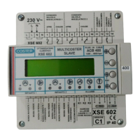
5. OVERALL DIMENSIONS 6. FRONT PANEL
1
2
3
3
4
5
4. TECHNICAL DATA (default values in bold print)
• Electrical data
Power supply 24 V ~ ± 10%
Frequency 50 … 60 Hz
Consumption 5 VA
Protection IP40
Radio interference VDE0875/0871
Vibration test with 2g (DIN 40 046)
Voltage-free output contacts:
maximum switching voltage 250 V ~
maximum switching current 5 (1) A
Construction standards Italian Elechtrotech Comm. (CEI)
Data storage period 5 years
Software Class A
• Mechanical data
Case Modulo DIN 6E
Mounting on DIN 35 rail
Materials:
base NYLON
cover ABS
Room temperature:
operating 0 … 45°C
storage – 25 … + 60°C
Room humidity Class F DIN 40040
Dimensions 105 x 115 x 71.5
Weight 0.6 kg
• Programs and yearly periods
24-hour programs 1…25
24-hour schedules 2…6
7-day programs 1…5
Yearly periods 0…25
• Setting range
Heating (or cooling) temperatures:
desired room temp. (B3 o B1+B3) 0…20 (25)…40 °C
desired flow temp. (B1) 0…20 (25)…60 °C
min. flow limit (B1+B3) 1…18 (8)…60 °C
max. flow limit (B1+B3) 1…50 (25)…60 °C
room heating flow limit (B1+B3) 0…40 °C
room cooling flow limit (B1+B3) 0…40 °C
outside default temp. (B1+B2) –30…–10 (35)…40 °C
flow default temp. (B1+B2) 1…50 (10)…60 °C
summer compensation Te–Ta (B2+B3) 0…6…20 °C
Preheating or dewpoint temperature (B4) :
min. limit 0…10…40 °C
adjustment – 9,5…0…+9,5 °C
Heat pump min. outside temp. –30…0…40 °C
1 - Alphanumeric display 6 - Fan warning
2 - + and – operating keys 7 - Humidifier warning
3- ← and →operating keys 8 - Frostprotection warning
4 - Valve warnings 9 - Air damper warning
5 - Pump warning 10 - Readings alarm warning
11 - Malfunction warning
1 – Electronic component protection cover
2 – Support base with transformer, relays and terminal boards
3 – Screws for securing cover to base
4 – DIN rail securing elements
5 – DIN rail release lever
Temp. proportional band (base value):
Heating (room) (B3 o B1+B3) ±1…
±2 …± 40 °C
Heating (flow) (B1) ±1…
±10…±40 °C
Various temp. proportional band multipliers:
Heating flow (B1+B3) Pb amb x 0.5…5…20
Cooling temperatures Pb heat x 0.5…20
preheating (B4) Pb heat disch x 0.5…1…20
dew point (B4) Pb room heat x 0.5…1…20
air dampers (B2+B3) Pb room heat x 0.5…1…20
frostprotection battery (B7) Pb flow heat x 0.5…1…20
Temp. integral time 0…10…255 min.
Room or flow relative humidity (B6) :
humidification 0…50…99 %
dehumidification 0…60…99 %
Humidity proportional band ±0,5…±6 …± 40 %
Humidity integral time 0…10…255 min.
Y output control: – modulating
– 2 stage
– 3 stage
Ys output control 0…10 V–
Valve stroke time (modulating) 30…120…630 sec.
Season switching: – manual (display)
– external control
– auto based on outside temp.
– auto based on room temp.
– auto based on dates
Season switching outside temperatures:
winter 0…20…40 °C
summer 0…25…40 °C
Season switching delay based on outside temp.:
winter 1…24…60 ore
summer 1…4…60 ore
• Alarm setting
Telemanagement (PC-controlled calibrations)
Alarm call attempts 1…5…255
Alarm call interval 2…10…255 m
Alarms (PC-controlled calibrations)
Flow temp. diff. threshold (B1) 0…5…99 °C
Flow temp. diff. delay 2…30…255 min.
Room temp. diff. threshold (B3) 0…1…99 °C
Room temp. diff. delay 2…30…255 min.
Frostprotection temperature trip delay (B4) 2…5…255
min.
Humidity diff. threshold (B6) 0…10…100 %
Humidity diff. delay 2…30…255 min.
Warning :
In case of static, the equipment’s output controls may change
settings; original settings will be subsequently restored
automatically.
105
115
35
50.5 21
45
AIR TREATMENT
CONTROLLER
DTU 614
COSTER
VALVE HUMIDIFICATOR
+
–
▼
▼
1
2
°c
!
ALARMSPUMP FAN
ESC
FROSTPROT.
❄
DAMPER
1 2
4 5 6 7 8 9 11 310
 Loading...