4
G 521 - RFG 361 C1 Eng. 25.11.08 MZ Rev. 02
We reserve the right to make changes without notice
COSTER
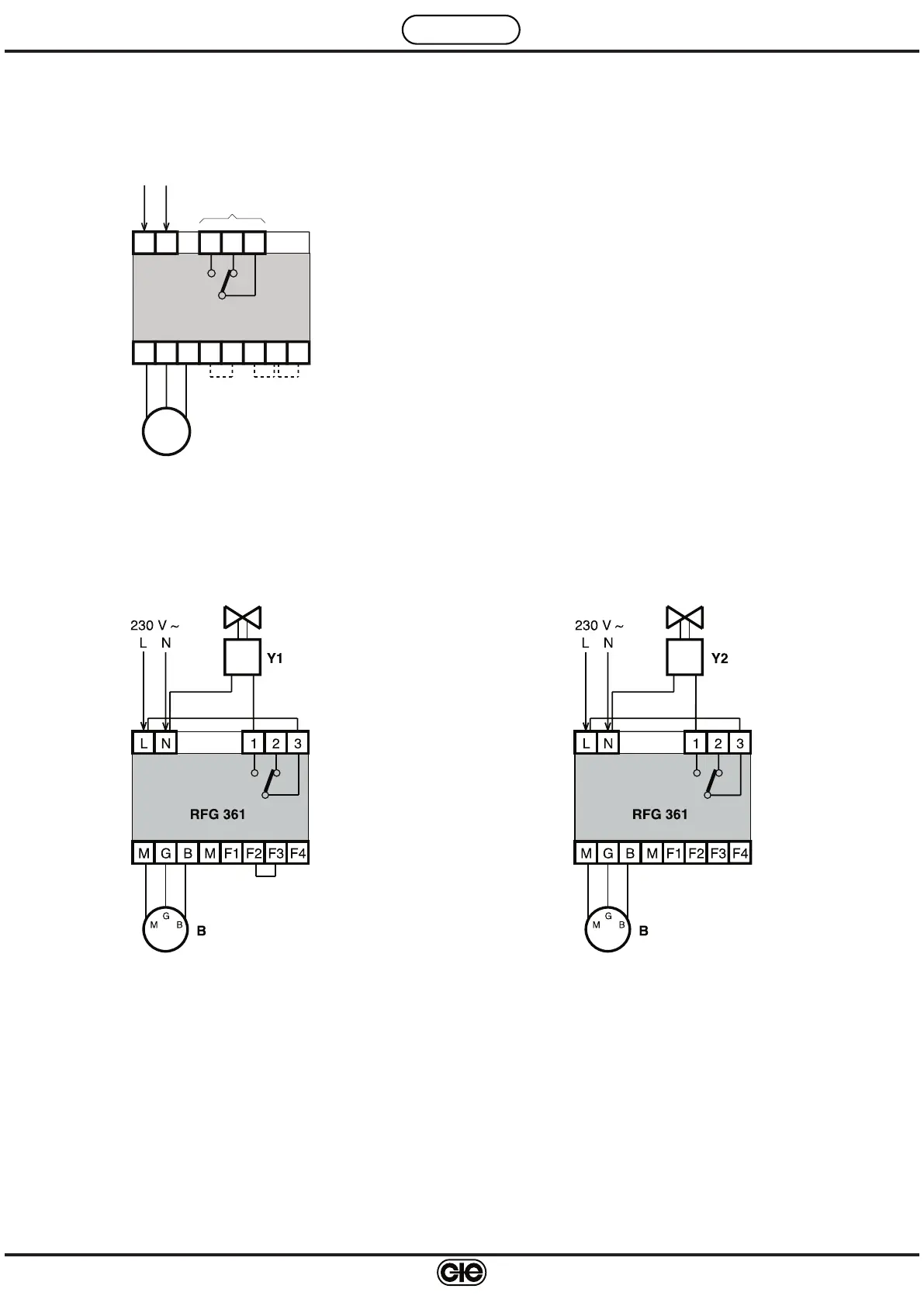
8. WIRING DIAGRAMS
Functions of jumpers
M-F1 – without jumper = internal and external alarms ena
-
bled
with jumper = internal and external alarms disabled
F2-F3 – without jumper = relay normally energised,
with gas leak de-energised
with jumper= relay normally de-energised,
with gas leak energised
F3-F4 – without jumper= with latching of alarm with jumper
with jumper= without latching of alarm
WARNING: before changing the position of the operational
jumpers switch off power
.
N. B. : the relay switch is shown in the condition of thedevice
not being powered
.
B – Gas monitoring sensor
8.
1 General diagram
8.
2.2 Diagram of wiring with N.C. valve (230 V~)
8.2 Examples of wiring
8.
2.1 Diagram of wiring with N.O. valve with manual reset
(230 V~)
B – Gas monitoring sensor
Y1 – N.O. solenoid valve with manual reset
B – Gas monitoring sensor
Y2 – N.C. solenoid valve
The normally-closed valve (without manual reset) is the prefer-
red valve for boilers and boiler rooms in general.
Its use is NOT recommended, however, where there are open
flames (e.g. gas hob) if not provided with a device for shutting
off the gas in the absence of the flame.
BGM
RFG 361
L N
B
F2F1M F3 F4
BM
G
1 2 3
Operational
control
N
230 V ~
L