Do you have a question about the Coster RGS 128 and is the answer not in the manual?
Details on sensors, gas types, power, protection, and connection length.
Lists sensing elements for Methane, LPG-propane, and CO.
Specifies alarm and pre-alarm levels for different gases.
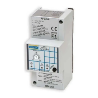
Identifies front panel elements like LEDs and buttons.
Identifies components shown in the base diagram.
Guidelines for positioning detectors and sensors based on gas type.
Precautions for installing shut-off solenoid valves.
Details default programmer settings for sensors and latching.
Explains programmer settings based on sensor configuration.
Describes programmer options for latching alarm behavior.
Explains programmer settings for output relay operation.
Shows the overall wiring diagram for the detector and sensors.
Illustrates wiring for solenoid valves and fans in different modes.
Specifies cable types and sizes for power and sensor connections.
Describes the initial power-on sequence and sensor stabilisation period.
Explains how pre-alarm and alarm states are indicated by LEDs.
Details alarm and pre-alarm thresholds for methane and LPG-propane.
Specifies CO alarm and pre-alarm thresholds and intervention modes.
Describes how sensor faults are indicated and what action to take.
Explains the two operating modes for the SPDT output relay.
Describes how the detector maintains alarm status.
Details the steps for performing a detector self-check.
How to check if remote sensors are powered and working.
Information on sensing element lifespan and replacement requirements.
Safety actions to take in case of combustible gas alarm.
Safety actions to take in case of carbon monoxide alarm.
This document describes the Coster RGS 128 - 228 series of domestic microprocessor-based selective gas detectors with relay output. These devices are designed to ensure the safe use of domestic gas appliances in non-industrial premises by monitoring the concentration of combustible gases (methane, LPG-propane) and carbon monoxide (CO) in the air.
The RGS 128 - 228 detectors are capable of monitoring gas concentrations using an internal sensor and can be expanded with one or two optional remote sensors. The internal sensor is supplied for methane (RGS 128) or LPG (RGS 228). Remote sensors can be connected for methane (SRS 158), LPG (SRS 258), or carbon monoxide (SRS 358).
The detectors provide a SPDT (Single Pole Double Throw) relay output, which can control external devices such as gas shut-off valves or fans. Visual indicators include LEDs for power, pre-alarm, alarm, and sensor fault. An internal acoustic alarm is also integrated.
Upon power-up, the detector undergoes a stabilization period of 120 seconds, during which the green power LED flashes intermittently. After stabilization, the green LED remains lit, indicating the detector is ready for monitoring.
The sensing elements continuously monitor gas concentration. If a pre-alarm threshold is exceeded, the red LED starts flashing. If the alarm threshold is also exceeded, the red LED lights steadily, the internal acoustic alarm activates, and the output relay closes after a maximum delay of 30 seconds (to prevent false alarms from temporary gas presence).
For combustible gases (methane and LPG-propane), the alarm threshold is set at 0.80% (8,000 ppm) for methane and 0.35% (3,500 ppm) for LPG-propane, which is not greater than 20% of the Lower Explosive Limit (LEL). The pre-alarm threshold is set at 60% of the alarm threshold.
For carbon monoxide (CO), the detector operates based on both concentration and exposure time due to CO's high toxicity.
The detector also features a sensor fault alarm, indicated by a flashing yellow LED on the detector for an internal sensor fault, or flashing yellow LEDs on both the detector and the defective remote sensor for an external sensor fault.
The output relay can be configured for two operating modes:
The alarm latching behavior can also be configured:
The detector is designed for easy installation on a wall or standard flush-mounting pattress. It includes a knockout for cable passage. The device is constructed with a shockproof plastic base and protective cover.
The programmer (5.13) allows configuration of the output relay mode (normally energised/de-energised) and alarm latching behavior (with/without latching). It also allows setting the sensor configuration (internal sensor only, with B2, or with B2 and B3 remote sensors). Incorrect programmer settings will trigger a sensor fault signal (yellow LED).
Installation guidelines specify optimal positioning for detectors and remote sensors based on gas type:
Detectors and sensors should avoid being placed near gas boilers/water-heaters (less than 1-2m), hobs/ovens (less than 2-3m), in open spaces, enclosed spaces, directly above/below sinks, near doors/windows, near air extractors, in areas with extreme temperatures/humidity, dust/dirt, restricted air movement, or water splashing.
The shut-off solenoid valve, if used, should be installed on the gas supply pipe, preferably in a separate, easily accessible space, protected from weather if outside, and downstream of pressure reduction valves.
Electrical connections for power supply and control circuits should use 1.5 mm² cables. Remote sensor connections require 1 mm² for distances up to 50 meters, or 1.5 mm² for distances up to 75 meters. The detection system must always be powered directly from the mains supply without interposing switches that could inadvertently disable it.
Periodic maintenance is crucial to ensure correct operation.
Sensing elements have a limited lifespan, indicated by a servicing date on the sensor cover. After this date, the sensing element must be replaced and the sensor recalibrated by the manufacturer's workshops.
In case of a "Sensor fault" warning, technical assistance should be sought.
In the event of an alarm, users are advised to:
| Brand | Coster |
|---|---|
| Model | RGS 128 |
| Category | Gas Detectors |
| Language | English |