3
G 221 - RGS 128-228 Eng. 25.11.08 MZ REV. 01
We reserve the right to make changes without notice
COSTER
7. INSTALLATION
The gas detector must be installed in the space in which a gas escape is most likely to occur e.g. the kitchen with
its hobs, oven, wall boiler.
If the gas appliances used are to be found in several rooms, it is possible to connect one or two remote sensors
to the detector (which already has an internal sensor) in order to guarantee a complete control of all the spaces
concerned.
The correct siting of the components forming the gas-detecting system is essential for ensuring its correct
operation and accordingly for guaranteeing the safety of the spaces controlled and of the persons in them.
For this reason you advised to have your system installed by a qualified engineer.
7.
1 Detector and remote sensors
The siting of the detector and of any remote sensors depends on the type of gas and, in particular, on the concen
-
tration in air of the gas that has to be controlled
:
– Methane
(a gas lighter than air that tends to move upwards). Position: at a distance of 10...50 centimetres from
the ceiling and, in any event, above the door or the highest window.
.
– LPG-propane
(a gas heavier than air that tends to move downwards). Position: at a distance of 10...30 centimetres
from the floor
,
– CO (carbon monoxide)
(a gas with a density similar to air and which therefore tends to diffuse uniformly). Position:
at a height of 150... 200 centimetres from the floor.
Moreover, to ensure correct operation and to avoid false alarms due to the casual and momentary presence of gas,
the detector and the sensors must NOT be positioned :
– at a distance less than 1...2 metres from gas boilers or water-heaters.
– at a distance less than 2...3 metres from gas hobs and ovens (also to avoid contamination of the sensor by fats
and kitchen vapours.
– in the open.
– in enclosed spaces (e.g. behind curtains, in a corner or in a wardrobe).
– directly above or below a sink.
– near to doors or windows.
– near to air extractors.
– in places where temperature and humidity could be outside the limits given under 3.TECHNICAL DATA.
– in places where dust or dirt could contaminate the sensor and so render it ineffective.
– in places where air movement could be restricted by furniture.
– in places subject to water splashing, especially for detectors sited near the floor.
– in places where it would be very difficult to re-set the device manually and to make periodic checks.
7.
2 Shut-off solenoid valve
This must be installed on the gas supply pipe, observing the following precautions:
– preferably in a space different from the one monitored.
– in an easily accessible place (especially for the valves which have to be re-set manually).
– if installed outside, it must be protected from the weather.
– in plants with external tanks of LPG-propane it must be installed downstream of the pressure reduction valve
(30...40 mbar).
– in plants with cylinders, it must be installed downstream of the pressure reduction valve and, if possible, connected
directly to this by means of a screwed pipe.
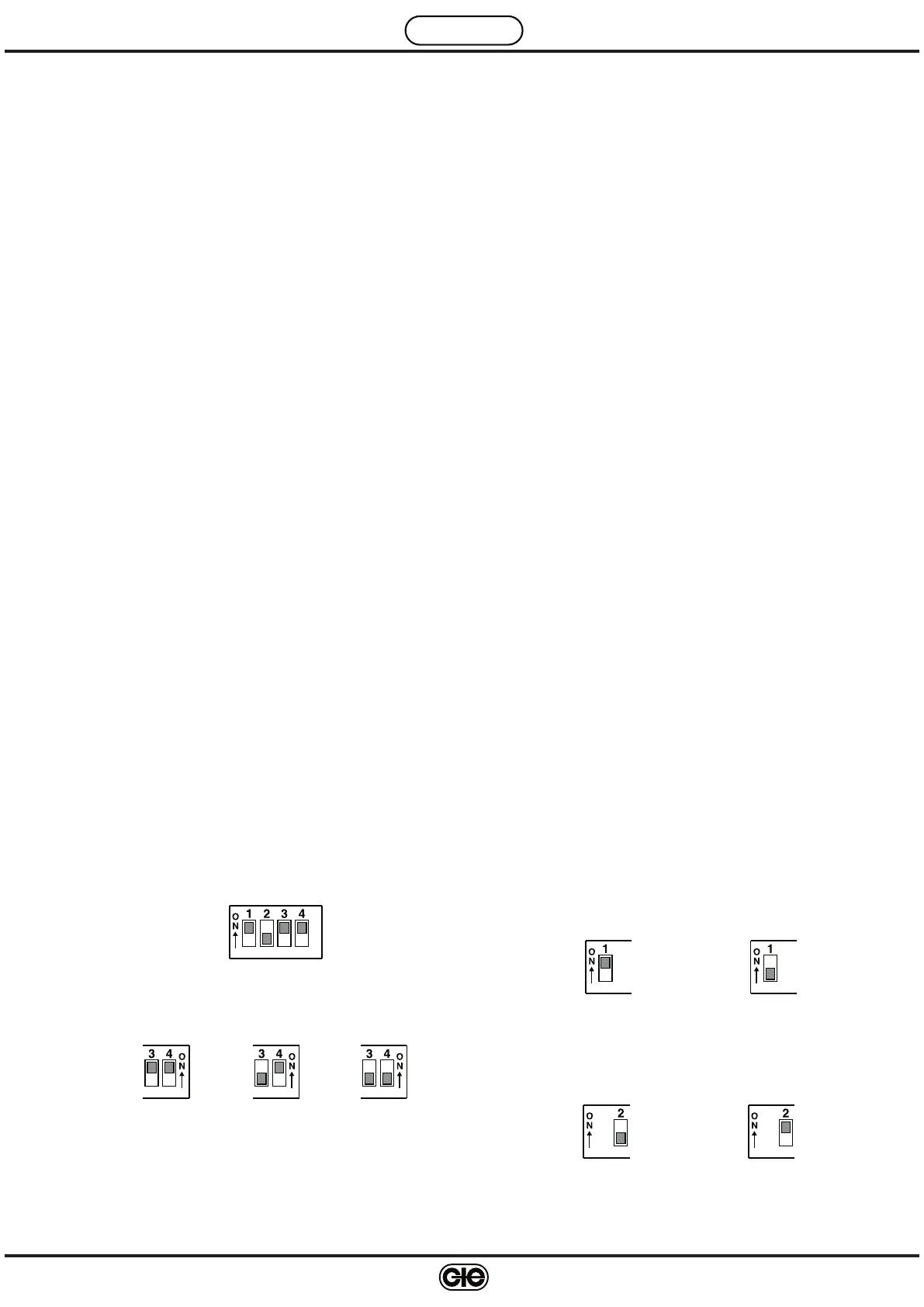
8. PROGRAMMER
Connection sensor
Internal sensor only With B2 With B2 and B3
If the programmer is not set according to the actual situation of
the sensors, the detector will signal fault status with the yellow
LED (3.
3)
Factory setting
Output relay
Normaly energised Normaly de-energised
Latching alarm
With latching Without latching
 Loading...