2
G 221 - RGS 128-228 Eng. 25.11.08 MZ REV. 01
We reserve the right to make changes without notice
COSTER
6. CONSTRUCTION
The detector comprises:
– base (4.
1, 5.1) in shockproof plastic, with two holes at a standard distance (5.3) for mounting on a wall or on a
standard flush- mounting pattress and with a knockout (5.4) for the passage of the electric cables.
– printed circuit (5.2), manufactured to CEI standards, where are fitted the terminal block for the electrical connections
(5.9 and 5.10), the gas sensor (5.11), the acoustic alarm (5.12), the output relay hermetically-sealed to prevent
sparks from switching comeing into contact with the surrounding atmosphere and with the switches enclosed in
inert gas to protect them from wearing out (5.
8); the button for re-start from the latching condition and testing (4.6,
5.15), the microprocessor (5.14) and the programmer (5.13).
– protective cover (4.2), in shock-proof plastic, which is secured by means of two securing elements (5.5) on the left
and by the cover locking tongue (5.6) on the right.
3. TECHNICAL DATA
Power supply 230 V ~ ± 10%
Frequency 50…60 Hz
Consumption 2,5 VA
Protection IP 42
Electromagnetic compatibility CEE 93/68
Ambient temperature::
– operating 0…40 °C
– storage – 20…+ 60 °C
Permitted ambient humidity Classs F DIN 40040
Weight 250 g
SPDT output relay :
– type
watertight with inert gas
– maximum switching voltage 250 V ~
– maximum switching current 5 (1) A
Acoustic alarm: 85 db / 1 metre
Time for stabilisation sensors 120 seconds
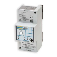
4. OVERALL DIMENSIONS
1 – Base 4 – Alarm LED
2 – Cover 5 – Power LED
3 – Sensor fault LED 6 – Button for TEST and for re-
starting operation
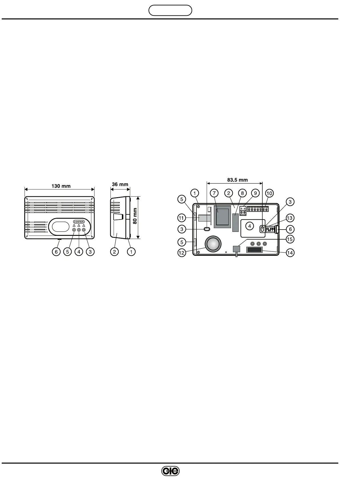
5. BASE
1 – Base 9 – Power supply terminal block
2 – Printed circuit 10 – Terminal block for controls
3 – Holes for fixing screws & remote sensors
4 – Knockout for cables 11 – Internal gas sensor
5 – Cover securing elements 12 – Acoustic alarm
6 – Cover locking tongue 13 – Programmer
7 – Transformer 14 – Microprocessor
8 – Output relay 15 – Button for TEST and re-start
operation
Sensing element:
– Methane (RGS 128, SRS 158):
semiconductor (Figaro TGS 2611-B00)
– LPG-propane (RGS 228, SRS 258):
semiconductor (Figaro TGS 2610-B00)
– CO (carbon monoxide) (SRS 358):
electrochemical cell (Sixth-Sense ECO-Sure/2e
)
Alarm and pre-alarm thresholds:
– Methane alarm 0.80 % (8,000 ppm)
– Methane pre-alarm 60% of alarm threshold
– LPG-propane alarm 0.35 % (3,500 ppm)
– LPG-propane pre-alarm 60% of alarm threshold
– CO (carbon monoxide) alarm
“threshold + time”
< 50 ppm: no alarm
50…100 ppm: 60 minutes
100…300 ppm: 10 minutes
> 300 ppm: immediate alarm
– CO (carbon monoxide) pre-alarm time between
exceeding threshold and alarm
 Loading...