4
G 221 - RGS 128-228 Eng. 25.11.08 MZ REV. 01
We reserve the right to make changes without notice
COSTER
10. ELECTRICAL CONNECTIONS
The power line for the remote sensors can be the same as that of the detector or taken separately from another
point in the distribution network
.
IMPORTANT : the detection system must always be in operation, so the electric power for the detector and the
remote sensors must be taken directly from the mains supply, without the interposition of switches
or other devices that could inadvertently render it inactive
.
For the electrical connections the following cables should be used :
– 1.5 mm
2
for power supply and for the control circuit (relay output switch),
– for connection of the remote sensors :
– 1 mm
2
for distances up to 50 meters,
– 1.5 mm
2
for distances up to 75 meters
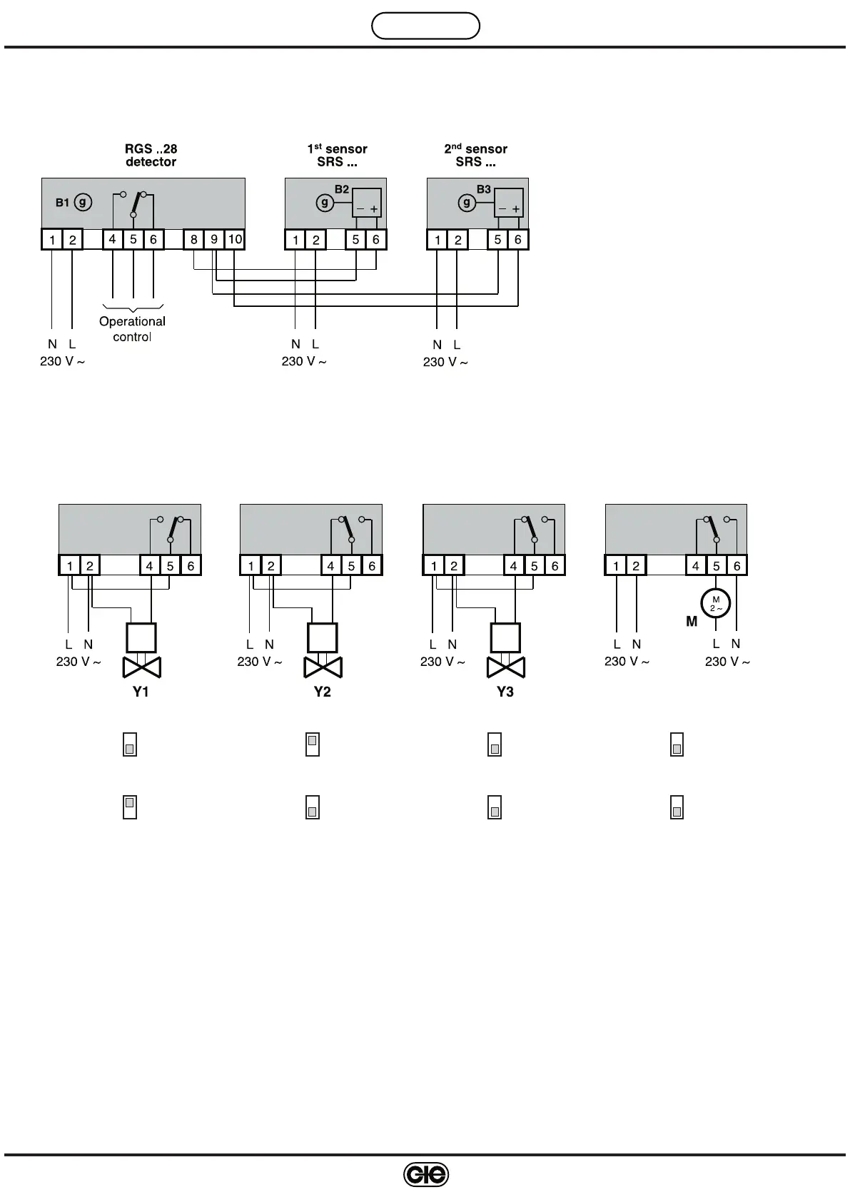
9. WIRING DIAGRAMS
GENERAL LAYOUT
The relay is shown with the detector in the "detector not
powered" condition
EXAMPLES OF OPERATIONAL CONTROLS
The relay is shown with the detector “powered and not in alarm” condition
Solenoid valve Solenoid valve Solenoid valve
N.O. with re-set N.C. N.C. with re-set Fan
(solution not recommended
with kitchen gas hobs
)
Without latching With latching Without latching Without latching
Relay normally de-energised Relay normally energised Relay normally energised Relay normally energised
2
On
1
On
1
On
1
On
1
On
2
On
2
On
2
On
B1 – Internal sensor of detector
B2-B3 – SRS… remote sensors
M – Fan
Y1 – Solenoid valve N.O with re-set
Y2 – Solenoid valve N.C with re-set
Y3 – Solenoid valve N.C with re-set
 Loading...